background image

WZDS9100 #2 


1


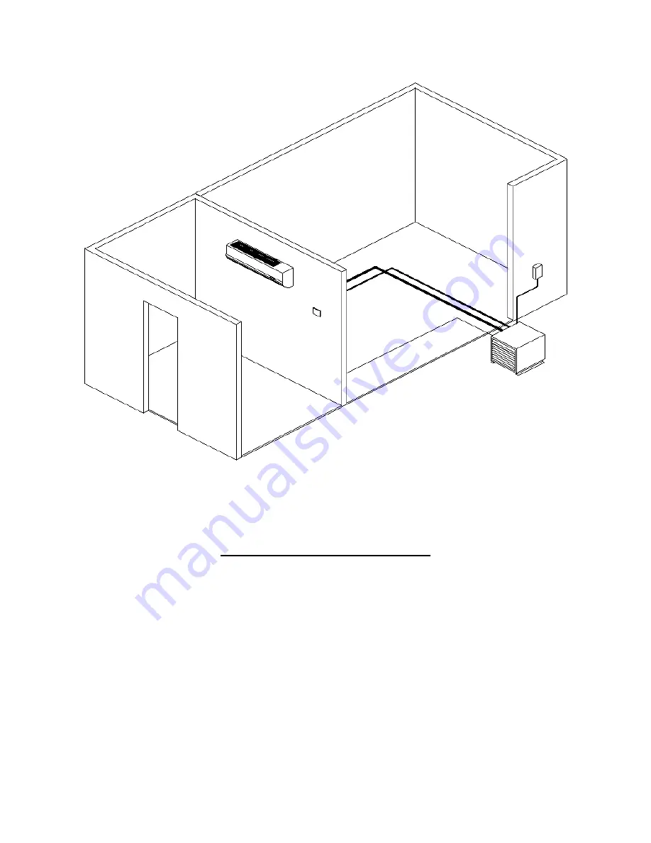
Wine Zone Ductless Split System 


Requires an HVAC technician to install and charge unit 


Can be charged with R-22, NU-22B, MO99, or R-427A refrigerants 


Electric connections for evaporator are hard wired to the condenser 


Industrial grade for longer life 


Indoor and outdoor condensing units available 


Field supplied drain line, refrigerant, and electric connections required  

Summary of Contents for WZDS9100

Page 1: ...charge unit Can be charged with R 22 NU 22B MO99 or R 427A refrigerants Electric connections for evaporator are hard wired to the condenser Industrial grade for longer life Indoor and outdoor condensing units available Field supplied drain line refrigerant and electric connections required ...

Page 2: ...ssembled outdoor upgrade kit if ordered 3 Wall mounted evaporator modified for system 4 Thermostat 5 50 ft of 3 8 x 5 8 line set 6 Filter drier may be factory installed 7 Sight glass may be factory installed 8 Fan cycle control mounted and wired 9 Wiring diagrams 10 Installation instructions with copy of Diagnostic Sheet 11 Warranty information with copy of Diagnostic Sheet A qualified service tec...

Page 3: ...ront of the rack 2 Place the condenser at the desired location outside the wine cellar in a well ventilated area or outdoors Indoor condensers must be placed in a space twice the volume of the wine cellar to prevent excessive condensing temperatures Check local codes for proper venting of mechanical rooms Field supplied vibration absorbing mounting pads and insulated compressor jackets effectively...

Page 4: ... with oil We highly recommend using rigid copper for this reason For systems with condensers 10 feet or more above the evaporator reduce the suction line size by one For example 5 8 line changes to 1 2 and 7 8 changes to 3 4 for the vertical section of the line only Install a P trap at the bottom of the riser of the same size as the horizontal piping Line sets up to 80 equivalent feet will use 3 8...

Page 5: ...ever expose the system to leak test pressures greater than 150 PSI Test all fittings including factory installed flare fittings on condenser and evaporator that may have loosened during shipping Leaks on unit s from a result of loose valves interconnecting fittings and or field piping are not covered by the warranty It is the installer s responsibility to locate and repair all leaks prior to start...

Page 6: ...h an accurate digital thermocouple style thermometer 12 Allow the wine room temperature to fall to 55 F Check the super heat at the evaporator Measure the suction pressure at compressor access port From refrigerant pressure temperature tables determine the saturation temperature for R 22 or the dew temperature for NU 22B or other blended refrigerant at the observed suction pressure Measure the suc...

Page 7: ...he head pressure at the receiver service valve 4 ICM333 Head Pressure Control See step 10 on page 6 5 Liquid line Measure the liquid line temperature here to determine sub cooling 6 Filter drier 7 Sight glass 8 Thermostatic expansion valve See step 12 on page 6 9 Suction line Measure the suction pressure at the compressor suction service valve Measure the suction line temperature near the compress...

Page 8: ...tes a cutout in the unit casing Using the cutout will leave the refrigerant piping condensate drain and electric exposed in the cellar and should be avoided Numbers 1 and 3 indicated below are for piping routes that will leave the refrigerant lines drain and electric concealed and should be used for the most attractive installation A single 2 or 2 hole will accommodate the passage of the line set ...

Page 9: ...of the evaporator casing can easily be removed Screws are concealed under plastic covers on the bottom leading edge of the unit under the air discharge louver Remove the covers to expose the screw heads and remove the screws Remove screws above the air discharge under the hinged filter cover Pull out and lift the bottom of the evaporator casing to uncover the electric hook up After installation pr...

Page 10: ...ted after the walls are finished Use caution when using the alternate route Secure the piping above the bend before turning the piping to prevent kinking the suction line A qualified service technician must record all of the information on the diagnostic sheet before calling for technical assistance The technician must be able to identify the unit with the order number and serial numbers to receiv...

Page 11: ...tting Drain Fitting Power Supply Weight Max Fuse A B C WZDS9100 45 WB036 49 12 7 8 9 1 8 3 8 MF 5 8MF 5 8 Barbed 208 240 60 1 37 lbs 15 You must install a line set according to Table 1 on page 4 Field supplied reducers may be required Reduce at the evaporator and condenser connections A minimum of 4 clearance required on top and bottom 2 of clearance required on each side ...

Page 12: ...supplied reducers may be required Reduce at the evaporator and condenser connections Minimum of 12 clearance required on each side of unit Model dB Length In inches Width in inches Height in inches Liquid Line Fitting Suction Line Fitting Wt In lbs Power Supply Min Circuit Amps Max Fuse WZDS9100 OC 58 27 24 5 22 3 8 SW 5 8 SW 170 208 230 60 1 11 0 15 Model dB Length In inches Width in inches Heigh...

Page 13: ...ier System Ground Lug Above Terminal Boards Electrical Requirements 1 Check the Copeland rating plate located on top of the condenser coil for proper voltage maximum fuse run load amperage and wire size 2 Line voltage from service panel for cooling unit The power circuit connects to terminals L1 and L2 on TB1 in the condenser control panel 3 The evaporator circuit connects to terminals marked EVAP...

Page 14: ...e condenser control panel 2 Load voltage for the ductless evaporator will come from terminals marked EVAP on TB1 in the condenser control panel Connect these wires to the small terminal block with the evaporator fan motor wires attached Attach the ground wire to the terminal with the green or green and yellow striped wire 3 Each unit must be installed in accordance with the National Electric code ...

Page 15: ...ntrol panel Thermostat terminal C connects to terminal C on TB2 in the condenser control panel Thermostat terminal G connects to terminal G on TB2 in the condenser control panel Use quality 18 gauge thermostat wire Read and follow the manufacturer s installation instructions We recommend you enter the Installer Setup in the Honeywell Installation Guide and choose the following settings 1 System ty...

Page 16: ...p for using this thermostat with a WineZone system For detailed installation and troubleshooting instructions please refer to the manufacturer s instructions included with the thermostat Install the Wallplate 1 Position the wallplate on the wall with the directional arrow pointing up and the terminal blocks facing outward 2 Pull equipment wires through the wallplate wiring passage 3 Use a level to...

Page 17: ...te on 24 VAC power and or two AA batteries both are recommended Using 24 VAC with AA battery backup is highly recommended Wiring 24 VAC Common Single Transformer system Connect the common side of the transformer to the C screw terminal of the thermostat wallplate Assure that the metal jumper connects RC and RH Connect power side to the RC RH and assure that the jumper remains in place Install Batt...

Page 18: ...S Format 110 System Type 1 13 1 1 1 Heat 1 Cool conventional 120 Fan Control heating 0 1 0 1 Electric furnace thermostat controls heating fan 150 Backlight 0 1 0 0 Backlight temporarily on 170 Remote Sensor 0 5 0 0 No sensor 1 Indoor sensor if used 180 Heat Pump Compressor Lockout 0 45 0 0 No sensor 190 Heat Pump Auxiliary Lockout 0 60 0 0 None 230 Furnace Filter Change Reminder 0 30 60 90 120 365...

Page 19: ...lay Icons 0 4 0 0 Time Temp SP 530 Revision Not Adjustable 540 Factory Default Reset 0 1 0 0 Disable 600 System Test Main Output Cool 0 2 0 0 Disable 610 System Test Main Output Heat 0 3 0 0 Disable 620 System Test Fan Output 0 1 0 0 Disable 630 System Test Emergency Output 0 1 0 0 Disable emergency output 640 System Test Economizer 0 1 0 0 Disable economizer output IMPORTANT Some humidity control...

Page 20: ...ayed on the touchscreen The condenser and indoor fan should go off Nothing should be running 9 Set the Humidity setpoint above the humidity displayed on the touchscreen The humidifier should come on 10 Set the temperature to 55 and the Humidity to 65 Humidifier Installation Install the Wine Guardian Freestanding Humidifier Run the humidifier prior to installation as the warranty does not cover rem...

Page 21: ...e from service panel Y Thermostat Y CCH Crankcase heater CCH Crankcase Heater C Thermostat C FM Fan motor CCH Crankcase Heater G Thermostat G FR Evaporator fan relay A Thermostat A Humidity GND Ground EVAP 230V load voltage to evaporator TB Terminal Board EVAP 230V load Voltage to evaporator TR Transformer COMP Compressor HUM Humidifier COMP Compressor HUM Humidifier ...

Page 22: ...d start time is factory set to the minimum for sleeve bearing motors Adjust the set point dial to maintain 225 psi head pressure when the condenser ambient is at or below 70º F The control will maintain condenser pressure between 20 psig above and 20 psig below dialed Pressure Setpoint The ICM Pressure Transducer is located on the receiver backseat valve The backseat valve must remain open 1 2 to ...

Page 23: ...frigerants in liquid state 5 Adjust the condenser fan cycle control to maintain 225 PSI head pressure with condenser ambient temperatures at or below 90º F 6 Continue to add refrigerant until the sight glass is clear 7 Allow the unit run and cool the room to 55º F 8 Compare the saturation temperature corresponding to the suction pressure at the compressor to the sensible suction line temperature a...

Page 24: ...not calling for cooling Lower set point 4 Faulty thermostat or wiring Check low voltage wiring replace thermostat Unit runs but does not cool 1 Lack of air flow Check filter make sure louvers and fan are unobstructed Clean evaporator if necessary 2 Unit low on charge Add refrigerant 3 Compressor not running Check compressor and starting components 4 Unit undersized Call a qualified technician Evap...

Page 25: ...exceeds 260 or 1 Thermostatic expansion valve out of adjustment or faulty Check TXV operation Lower superheat see step 12 Suction pressure in evaporator too low or 2 Unit low on charge Add refrigerant Suction line temperature at compressor too high Humidity in cellar too low 1 Cellar vapor barrier not sufficient Install proper vapor barrier Condenser fan motor short cycles 1 Condenser fan motor pr...

Page 26: ...0 5 38 9 26 41 9 50 0 43 41 1 28 44 2 52 4 45 43 4 30 46 6 55 0 47 5 45 7 32 49 0 57 5 50 48 2 34 51 5 60 2 52 5 50 7 36 54 0 62 9 55 53 3 38 56 6 65 7 58 56 0 40 59 3 68 6 60 5 58 7 42 62 1 71 5 63 5 61 5 44 65 0 74 5 66 5 64 2 46 67 9 77 6 69 5 67 1 48 71 0 80 8 72 5 70 2 50 74 1 84 1 75 5 73 3 52 78 0 87 4 79 76 6 54 81 0 90 8 82 79 9 56 84 1 94 3 85 5 83 3 Bubble SATURATION Bubble Bubble 60 10...

Page 27: ...pper Suction pressure at compressor __________________________ Head pressure __________________________ Suction line temperature at compressor __________________________ Discharge hot gas line temperature __________________________ Liquid line temperature __________________________ Condenser ambient temperature __________________________ Return air temperature see above __________________________ ...

Reviews: