


250C7Y1B
Split system air conditioner
4PW34720-1G – 07.2010
Installation manual
7
5
For installation of the refrigerant branching kit (Refnet), refer to
the installation manual delivered with the kit.
6
Pipe connection
Be sure to perform a nitrogen blow when brazing.
(Brazing without performing nitrogen replacement or releasing
nitrogen into the piping will create large quantities of oxidized
film on the inside of the pipes, adversely affecting valves and
compressors in the refrigerating system and preventing normal
operation.)
Cautions for necessity of a trap
Since there is fear of the oil held inside the riser piping flowing back into
the compressor when stopped and causing liquid compression
phenomenon, or cases of deterioration of oil return, it will be necessary
to provide a trap at an appropriate place in the riser gas piping.
■
Trap installation spacing.
(See figure 16)
A
Outdoor unit
B
Indoor unit
C
Gas piping
D
Liquid piping
E
Oiltrap
H
Install trap at each difference in height of 10 m.
■
A trap is not necessary when the outdoor unit is installed in a
higher position than the indoor unit.
7.8.
Leak test and vacuum drying
The units were checked for leaks by the manufacturer.
After connecting the field piping, perform the following inspections.
1
Preparations
Referring to
figure 15
, connect a nitrogen tank, a cooling tank,
and a vacuum pump to the outdoor unit and perform the
airtightness test and the vacuum drying. The stop valve and
valves A and B in
figure 15
should be open and closed as shown
in the table below when performing the airtightness test and
vacuum drying.
2
Airtightness test and vacuum drying
■
Airtightness test:
Pressurize the liquid and gas pipes to 4.0 MPa (40 bar) (do not
pressurize more than 4.0 MPa (40 bar)). If the pressure does not
drop within 24 hours, the system passes the test. If the pressure
drops, check where the nitrogen leaks from.
■
Vacuum drying: Use a vacuum pump which can evacuate to
–100.7 kPa (5 Torr, –755 mm Hg)
1.
Evacuate the system from the liquid and gas pipes by using a
vacuum pump for more than 2 hours and bring the system to
–100.7 kPa. After keeping the system under that condition for
more than 1 hour, check if the vacuum gauge rises or not. If it
rises, the system may either contain moisture inside or have
leaks.
2.
Following should be executed if there is a possibility of moisture
remaining inside the pipe (if piping work is carried out during the
raining season or over a long period of time, rainwater may enter
the pipe during work).
After evacuating the system for 2 hours, pressurize the system
to 0.05 MPa (vacuum break) with nitrogen gas and evacuate the
system again using the vacuum pump for 1 hour to –100.7 kPa
(vacuum drying). If the system cannot be evacuated to
–100.7 kPa within 2 hours, repeat the operation of vacuum break
and vacuum drying.
Then, after leaving the system in vacuum for 1 hour, confirm that
the vacuum gauge does not rise.
7.9.
Pipe insulation
After finishing the leak test and vacuum drying, the piping must be
insulated. Take into account the following points:
■
Make sure to insulate the connection piping and refrigerant
branch kits entirely.
■
Be sure to insulate liquid and gas piping.
■
Use heat resistant polyethylene foam which can withstand a
temperature of 70°C for liquid side piping and polyethylene foam
which can withstand a temperature of 120°C for gas side piping.
■
If you think the temperature and the relative humidity around the
cooling pipes might exceed 30°C and RH 80%, reinforce the
insulation of the cooling pipes (at least 20
mm thick).
Condensation might be formed on the surface of the insulation.
NOTE
The pressure regulator for the nitrogen released when
doing the brazing should be set to 0.02 MPa or less.
(See figure 11)
Do not use anti-oxidants when brazing the pipe joints.
Residue can clog pipes and break equipment.
1
Pressure reducing valve
2
Nitrogen
3
Measuring instrument
4
Tank (siphon system)
5
Vacuum pump
6
Charge hose
7
Service port for adding refrigerant
8
Gas line stop valve
9
Liquid line stop valve
10
Outdoor unit
11
To indoor unit
12
Stop valve service port
13
Dotted lines represent on site piping
14
Valve B
15
Valve C
16
Valve A
1
Refrigerant piping
2
Location to be brazed
3
Nitrogen
4
Taping
5
Manual valve
6
Regulator
State
of the valves A and B
and the stop valve
Valve
A
Valve
B
Valve
C
Liquid
side
stop
valve
Gas
side
stop
valve
Performing the
airtightness test and
vacuum drying
(Valve A must always be
shut. Otherwise the
refrigerant in the unit will
pour out.)
Close
Open
Open
Close
Close
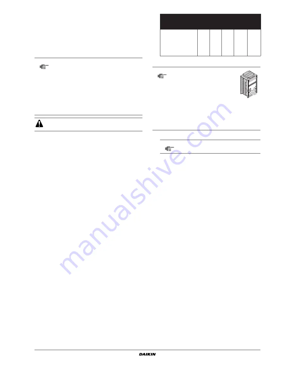
NOTE
Make sure to perform airtightness test
and vacuum drying using the service
ports of the stop valves of the liquid
side and of the gas side. (For the
service port location, refer to the
"Caution" label attached on the front
panel of the outdoor unit.)
■
See
"7.11. Stop valve operation procedure" on
page 8
for details on handling the stop valve.
■
To prevent entry of any contamination and to
prevent insufficient pressure resistance, always
use the special tools dedicated for working with
R410A refrigerant.
NOTE
Make sure to use nitrogen gas.


