background image

Operation Manual

SiBE041012

60

Operation Manual

2.11 WEEKLY TIMER Operation

Use the copy mode to make settings for Tuesday to Friday, because these settings are the same as 
those for Monday. 

23

WEEKLY TIMER Operation

„

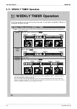
 Using in these cases of WEEKLY TIMER

[Monday]

Make timer settings up to programs 1-4. 

 Page 24

6:00

8:30

17:30

22:00

25˚C

27˚C

ON

ON

OFF

OFF

Program 1

Program 2

Program 3

Program 4

ON

OFF

ON

OFF

[Tuesday]

to

[Friday]

 Page 26

6:00

8:30

17:30

22:00

25˚C

27˚C

Program 1

Program 2

Program 3

Program 4

ON

OFF

ON

OFF

[Saturday]

No timer settings

[Sunday]

Make timer settings up to programs 1-4. 

 Page 24

8:00 10:00 

19:00 21:00 

27˚C

27˚C

25˚C

ON 

ON 

OFF 

OFF 

ON

OFF

OFF ON 

Program 1 

Program 2 

Program 3 

Program 4 

Up to 4 timer settings can be saved for each day of the week. It is convenient if the WEEKLY TIMER is set 
according to the family’s life style.

Example:  

The same timer settings are made for the week from Monday through Friday while different timer settings are 
made for the weekend.

• Up to 4 reservations per day and 28 reservations per week can be set in the WEEKLY TIMER. The effective use of the 

copy mode ensures ease of making reservations. 

• The use of ON-ON-ON-ON settings, for example, makes it possible to schedule operating mode and set temperature 

changes. Furthermore, by using OFF-OFF-OFF-OFF settings, only the turn off time of each day can be set. This will turn 
off the air conditioner automatically if the user forgets to turn it off.

Summary of Contents for RXG25J2V1B

Page 1: ...Applied Models Inverter Pair Heat Pump SiBE041012 Inverter Pair Wall Mounted Type J Series...

Page 2: ...SiBE041012 i Table of Contents Inverter Pair Wall Mounted Type J Series zHeat Pump Indoor Unit FTXG25JV1BW FTXG35JV1BW FTXG25JV1BS FTXG35JV1BS Outdoor Unit RXG25J2V1B RXG35J2V1B...

Page 3: ...tic Operation 19 1 7 Thermostat Control 20 1 8 NIGHT SET Mode 21 1 9 ECONO Operation 22 1 10 INTELLIGENT EYE Operation 23 1 11 Inverter POWERFUL Operation 24 1 12 Other Functions 26 2 Function of Ther...

Page 4: ...bnormality Indoor Unit 78 4 6 Front Panel Open Close Fault 79 4 7 Signal Transmission Error between Indoor Unit and Outdoor Unit 80 4 8 Unspecified Voltage between Indoor Unit and Outdoor Unit 81 4 9...

Page 5: ...r 142 1 12 Removal of Vertical Blade ASSY 145 2 Outdoor Unit 146 2 1 Removal of Outer Panels Fan Motor 146 2 2 Removal of Electrical Box 155 2 3 Removal of PCB 158 2 4 Removal of Reactor Partition Pla...

Page 6: ...er cable plug from the plug socket before disassembling the equipment for repair Working on the equipment that is connected to the power supply may cause an electrical shook If it is necessary to supp...

Page 7: ...ectrical shock Do not clean the air conditioner by splashing water Washing the unit with water may cause an electrical shock Be sure to provide the grounding when repairing the equipment in a humid or...

Page 8: ...at generation or fire When wiring between the indoor and outdoor units make sure that the terminal cover does not lift off or dismount because of the cable If the cover is not mounted properly the ter...

Page 9: ...vent children from swallowing it If a child swallows the coin battery see a doctor immediately Warning Caution Installation of a leakage breaker is necessary in some cases depending on the conditions...

Page 10: ...to install the packing and seal on the installation frame properly If the packing and seal are not installed properly water may enter the room and wet the furniture and floor For unitary type only Ca...

Page 11: ...SiBE041012 List of Functions 1 Part 1 List of Functions 1 Functions 2...

Page 12: ...t after Power Failure 3 D Airflow Self Diagnosis Digital LED Display COMFORT AIRFLOW Operation Wiring Error Check Comfort Control Auto Fan Speed Anti Corrosion Treatment of Outdoor Heat Exchanger Indo...

Page 13: ...SiBE041012 Specifications 3 Part 2 Specifications 1 Specifications 4...

Page 14: ...rd Air Filter Removable Washable Mildew Proof Removable Washable Mildew Proof Running Current Rated A 0 09 0 08 0 08 0 12 0 11 0 11 0 09 0 08 0 08 0 12 0 11 0 11 Power Consumption Rated W 18 18 18 24...

Page 15: ...r Filter Removable Washable Mildew Proof Removable Washable Mildew Proof Running Current Rated A 0 13 0 12 0 12 0 16 0 15 0 14 0 13 0 12 0 12 0 16 0 15 0 14 Power Consumption Rated W 26 26 26 32 32 32...

Page 16: ...iBE041012 6 Printed Circuit Board Connector Wiring Diagram Part 3 Printed Circuit Board Connector Wiring Diagram 1 Printed Circuit Board Connector Wiring Diagram 7 1 1 Indoor Unit 7 1 2 Outdoor Unit 1...

Page 17: ...or reduction motor front panel mechanism and limit switch 6 S46 Connector for signal receiver display PCB 7 S200 Connector for fan motor 8 H1 H2 H3 FG Connector for terminal board 9 JB Fan speed setti...

Page 18: ...nted Circuit Board Connector Wiring Diagram SiBE041012 8 Printed Circuit Board Connector Wiring Diagram PCB Detail PCB 1 Control PCB S42 S41 S32 JB JC S200 H3 H2 FG S46 S21 S25 LED A V1 F1U H1 2P25483...

Page 19: ...Printed Circuit Board Connector Wiring Diagram Printed Circuit Board Connector Wiring Diagram 9 PCB 3 INTELLIGENT EYE Sensor PCB PCB 2 Signal Receiver Display PCB S52 S51 S1W JA H2P H1P 3P254832 1 S36...

Page 20: ...PCB 2 S20 Connector for electronic expansion valve coil 3 S40 Connector for overload protector 4 S50 Connector for magnetic relay 5 S70 Connector for fan motor 6 S80 Connector for four way valve coil...

Page 21: ...rd Connector Wiring Diagram 11 PCB Detail PCB 1 Filter PCB PCB 2 Main PCB PCB 3 Forced Operation Button PCB HR1 HL2 S50 on main PCB 3P254234 1 FU1 HN2 S FU3 AC2 E1 E2 AC1 S11 V3 V2 S10 J5 S90 FU2 S100...

Page 22: ...on 23 1 11 Inverter POWERFUL Operation 24 1 12 Other Functions 26 2 Function of Thermistor 27 3 Control Specification 28 3 1 Mode Hierarchy 28 3 2 Frequency Control 29 3 3 Controls at Mode Changing St...

Page 23: ...g of Inverter The following drawing shows a schematic view of the inverter principle Phase Description 1 The supplied AC power source is converted into the DC power source for the present 2 The DC pow...

Page 24: ...tioning A fine adjustment is integrated to keep the room temperature constant Energy saving heating and cooling Once the set temperature is reached the energy saving operation enables to maintain the...

Page 25: ...over the fan banned area Control Flow Timing Chart Opening the front panel fully Start Running Output of the D signal after the front panel starts moving Making the fan rotate when the flap passes ove...

Page 26: ...uring heating mode the large flap directs airflow downwards to spread the warm air to the entire room Wide Angle Louvers The louvers made of elastic synthetic resin provide a wide range of airflow tha...

Page 27: ...In automatic fan speed operation upper limit is at M tap in 30 minutes from the operation start Heating On heating mode the fan speed is regulated according to the indoor heat exchanger temperature an...

Page 28: ...om temperature at start up and the target temperature is divided into two zones Then the unit operates in the dry mode with an appropriate capacity for each zone to maintain the temperature and humidi...

Page 29: ...controller Tc determines the target temperature Tt Tc 18 30 C 2 The target temperature Tt is calculated as Tt Tc C where C is the correction value C 0 C 3 Thermostat ON OFF point and mode switching p...

Page 30: ...ence returns to the zone C after being in the zone A The system resumes from defrost control in any zones except A The operation turns on in any zones except A The monitoring time has passed while the...

Page 31: ...hen automatically raises the target temperature slightly in the case of cooling or lowers it slightly in the case of heating This prevents excessive cooling in summer and excessive heating in winter t...

Page 32: ...tton When this function is activated the maximum capacity also decreases The remote controller can send the ECONO command when the unit is in COOL HEAT DRY or AUTO operation This function can only be...

Page 33: ...n cooling When a microcomputer does not have a signal from the sensor in 20 minutes it judges that nobody is in the room and operates the unit in the temperature shifted from the target temperature Co...

Page 34: ...monitored even in automatic operation in accordance with the mode of actual operation The lamp color changes according to the operation AUTO Red Blue DRY Green COOL Blue HEAT Red FAN White TIMER Orang...

Page 35: ...is displayed on the LCD 2 Select L light with the Temp or button 3 Press the Mode button to enter the brightness setting mode 4 Press the Temp or button to adjust the brightness of the multi colored...

Page 36: ...tton for 5 to 9 seconds while the unit is not operating Refer to Forced operation mode on page 41 for detail Note When the ON OFF button is pressed for 10 seconds or more the forced operation is stopp...

Page 37: ...pipe temperature used in place of the inner temperature of the compressor rises abnormally the operating frequency becomes lower or the operation halts 2 The discharge pipe thermistor is used for det...

Page 38: ...tail There are following modes stop cooling includes drying heating include defrosting Note Unless specified otherwise an indoor dry operation command is regarded as cooling operation Air conditioner...

Page 39: ...frequency among the frequency upper limits of the following functions Compressor protection input current discharge pipe temperature heating peak cut freeze up protection defrost 3 Determine lower li...

Page 40: ...not change for more than a certain fixed time the frequency is adjusted according to the D value When the D value is small the frequency is lowered When the D value is large the frequency is increase...

Page 41: ...ve coil switches from ON to OFF the OFF delay switch of the four way valve is carried out after the operation stopped Detail OFF delay switch of four way valve The four way valve coil is energized for...

Page 42: ...he discharge pipe temperature rises above a certain level the upper limit of frequency is set to keep this temperature from going up further Detail FCG 1 FCG 2 FCG 3 TCG 1 TCG 2 TCG 3 48 64 88 240 360...

Page 43: ...stopped Drooping zone The upper limit of the compressor frequency is defined as operation frequency 2 Hz After this the output frequency is pulled down by 2 Hz every second until it reaches the keep...

Page 44: ...heat exchanger temperature determines the frequency upper limit to prevent abnormal high pressure Detail R11818 Reset zone Up zone Keep zone Drooping zone Stop zone 0 C 5 C 7 C 9 C 13 C Reference Indo...

Page 45: ...speed of the outdoor fan is reduced by the command of the indoor outdoor quiet operation 7 Fan control for POWERFUL operation The rotation speed of the outdoor fan is increased while the POWERFUL ope...

Page 46: ...ure and the outdoor heat exchanger temperature The system is in heating operation The compressor operates for 6 minutes More than 28 minutes of accumulated time pass since the start of the operation o...

Page 47: ...sion valve control when the discharge pipe thermistor is disconnected Feedback Control 1 Discharge pipe temperature control Detail The followings are the examples of control which function in each mod...

Page 48: ...he discharge pipe temperature with the condensation temperature If the discharge pipe thermistor is disconnected the electronic expansion valve opens according to the outdoor temperature and the opera...

Page 49: ...ng is adjusted so that the actual discharge pipe temperature becomes close to the target discharge pipe temperature Indirect SH superheating control using the discharge pipe temperature The electronic...

Page 50: ...f the power consumption is below the specified value and the frequency is higher than the specified frequency it is regarded as refrigerant shortage The power consumption is small comparing with that...

Page 51: ...r for standby electricity saving make sure that the main power supply is turned OFF Item Forced Cooling Conditions 1 The outdoor unit is not abnormal and not in the 3 minute standby mode 2 The outdoor...

Page 52: ...2 2 AUTO DRY COOL HEAT FAN Operation 48 2 3 Adjusting the Airflow Direction and Rate 50 2 4 COMFORT AIRFLOW Operation 52 2 5 INTELLIGENT EYE Operation 53 2 6 POWERFUL Operation 55 2 7 OUTDOOR UNIT QUI...

Page 53: ...r method of using it In order to meet this expectation of the users giving sufficient explanations taking enough time can be said to reduce about 80 of the requests for servicing However good the inst...

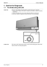
Page 54: ...lue DRY Green COOL Blue HEAT Red FAN White TIMER Orange INTELLIGENT EYE sensor It detects the movements of people and automatically switches between normal operation and energy saving operation Room t...

Page 55: ...models Open the front panel Air filter Earth terminal It is inside of this cover Drain hose Air outlet Model name plate Panel support plate Titanium apatite photocatalytic air purifying filter Outdoor...

Page 56: ...s anything to block signals between the unit and the remote controller such as a curtain the unit will not operate Do not drop the remote controller Do not get it wet The maximum distance for communic...

Page 57: ...R button Page22 CLOCK button QUIET button Page19 COMFORT button Page15 OFF TIMER button Page21 It cancels the timer setting Page21 22 SELECT button Page21 22 23 MODE selector button Page11 It selects...

Page 58: ...the operation mode In AUTO operation the system selects a temperature setting and an appropriate operation mode COOL or HEAT based on the room temperature at the start of the operation The computer c...

Page 59: ...g to use the air conditioner for a long period for example in spring or autumn turn the breaker off Use the air conditioner in the following conditions MODE Operating conditions If operation is contin...

Page 60: ...m the LCD To adjust the louvers at desired position Hold the knob and move the louvers Adjusting the Airflow Direction and Rate Press when the flaps have reached the desired position You will find a k...

Page 61: ...eful when adjusting the louvers Inside the air outlet a fan is rotating at a high speed Auto Indoor unit quiet Low Middle low Middle Middle high High When the airflow is set to indoor unit quiet opera...

Page 62: ...g air from blowing directly on the occupants of the room POWERFUL operation and COMFORT AIRFLOW operation cannot be used at the same time Priority is given to the function of whichever button is press...

Page 63: ...NTELLIGENT EYE lamp lights up Display To cancel INTELLIGENT EYE operation Press again disappears from the LCD The INTELLIGENT EYE lamp goes off INTELLIGENT EYE Operation INTELLIGENT EYE is the infrare...

Page 64: ...nits or humidi ers outside the sensor s detection area This sensor can detect undesirable objects Do not hit or violently push the INTELLIGENT EYE sensor This can lead to damage and malfunction Exampl...

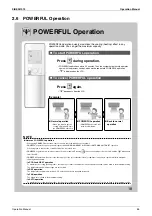
Page 65: ...any operation mode You can get the maximum capacity POWERFUL operation ends in 20 minutes Then the system automatically operates again with the previous settings which were used before POWERFUL operat...

Page 66: ...ation This is not available in FAN and DRY operation POWERFUL operation and OUTDOOR UNIT QUIET operation cannot be used at the same time Priority is given to the function of whichever button is presse...

Page 67: ...l not trip when the product runs alongside other appliances The maximum power consumption of the air conditioner is limited by using ECONO operation The circuit breaker will hardly trip even if the ai...

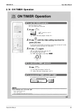
Page 68: ...e LCD and day of the week are displayed on the LCD NOTE Notes on TIMER operation NIGHT SET mode Timer functions are useful for automatically switching the air conditioner on or off at night or in the...

Page 69: ...tting time are displayed on the LCD The multi monitor lamp blinks twice The TIMER lamp periodically lights orange Display To cancel ON TIMER operation Press and setting time disappear from the LCD and...

Page 70: ...27 C 27 C 25 C ON ON OFF OFF ON OFF OFF ON Program 1 Program 2 Program 3 Program 4 Up to 4 timer settings can be saved for each day of the week It is convenient if the WEEKLY TIMER is set according to...

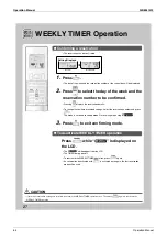
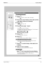
Page 71: ...day Pressing changes the reservation number and the day of the week 3 Press The day of the week and reservation number will be set and ON blink 4 Press to select the desired mode Pressing changes ON o...

Page 72: ...blink orange if all the reservation settings are deleted Display 10 Press to complete the setting is displayed on the LCD and WEEKLY TIMER operation is activated Page26 Be sure to direct the remote c...

Page 73: ...made once can be copied to another day of the week The whole reservation of the selected day of the week will be copied 2 Press to confi rm the day of the week to be copied 4 Press to select the desti...

Page 74: ...IMER operation The will disappear from the LCD The TIMER lamp goes off To reactivate the WEEKLYTIMER operation press again CAUTION 2 Press to select the day of the week and the reservation number to b...

Page 75: ...eservations WEEKLY TIMER operation will be activated The reservations for each day of the week This function can be used for deleting reservations for each day of the week It can be used while conf ir...

Page 76: ...cified Voltage between Indoor Unit and Outdoor Unit 81 4 9 Outdoor Unit PCB Abnormality 82 4 10 OL Activation Compressor Overload 83 4 11 Compressor Lock 84 4 12 DC Fan Lock 85 4 13 Input Overcurrent...

Page 77: ...ion device of the indoor or outdoor unit is activated or when the thermistor malfunctions 2 When a signal transmission error occurs between the indoor and outdoor units In either case conduct the diag...

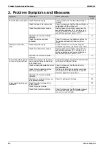
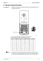
Page 78: ...ating operation cannot be used when the outdoor temperature is 24 C or higher and cooling operation cannot be used when the outdoor temperature is below 10 C Diagnose with remote controller indication...

Page 79: ...Note 1 A short beep pi and two consecutive beeps pi pi indicate non corresponding codes 2 To return to the normal mode hold the timer cancel button down for 5 seconds When the remote controller is lef...

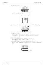
Page 80: ...to enter the service check mode The figure of the ten s place blinks 4 Press the Temp or button and change the figure until you hear the sound of beep or pi pi 5 Diagnose by the sound pi The figure of...

Page 81: ...pi The figure of the ten s place accords with the error code but the one s not beep The both figures of the ten s and one s place accord with the error code 9 Determine the error code The figures ind...

Page 82: ...Front panel open close fault 79 C9 Room temperature thermistor or related abnormality 78 Outdoor Unit E1 Outdoor unit PCB abnormality 82 E5 OL activation compressor overload 83 E6 Compressor lock 84...

Page 83: ...on of connector Troubleshooting Note Check the following connector Check the combination of the indoor and outdoor unit OK Check the connection of connectors See Note Correct the connection OK Error r...

Page 84: ...ng heating operation the temperature detected by the indoor heat exchanger thermistor is used for the heating peak cut control operation halt outdoor fan stop etc Malfunction Decision Conditions Freez...

Page 85: ...n the air filter Clean the indoor heat exchanger Replace the indoor unit PCB Replace the thermistor Does it conform to the thermistor characteristic chart Check the air filter Check the dust accumulat...

Page 86: ...is used to determine abnormal fan motor operation Malfunction Decision Conditions The detected rotation speed does not reach the demanded rotation speed of the target tap and is less than 50 of the ma...

Page 87: ...fan rotate smoothly Does the fan rotate Is the motor power supply voltage 310 340 VDC generated Is the motor control voltage 15 VDC generated Turn off the power supply and rotate the fan by hand Turn...

Page 88: ...pressor operation Supposed Causes Disconnection of connector Defective thermistor Defective indoor unit PCB Troubleshooting Check No 06 Refer to P 109 C4 Indoor heat exchanger thermistor C9 Room tempe...

Page 89: ...front panel 3 Turn on the power Wait until the initialization finishes 4 Operate the unit by the indoor unit ON OFF button YES YES YES YES NO NO NO NO Replace the harness and reduction motor Replace t...

Page 90: ...ply waveform Check the voltage of the connection wires on the indoor terminal board between No 1 and No 3 and between No 2 and No 3 YES YES Replace the indoor unit PCB Locate the cause of the disturba...

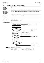
Page 91: ...ring of connecting wires Wrong indoor unit PCB or outdoor unit PCB mounted Defective indoor unit PCB Defective outdoor unit PCB Troubleshooting R11707 Caution NO YES YES YES NO NO Check the code numbe...

Page 92: ...PCBs Noise Momentary fall of voltage Momentary power failure etc Troubleshooting Caution Be sure to turn off the power switch before connecting or disconnecting connectors or parts may be damaged NO...

Page 93: ...tive stop valve Troubleshooting Check No 04 Refer to P 107 Check No 05 Refer to P 108 Check No 06 Refer to P 109 Check No 11 Refer to P 111 R11999 Caution YES NG Discharge pipe thermistor NO OK OK NG...

Page 94: ...f the power Disconnect the harnesses U V and W R8399 Caution NO YES YES NO NO YES Check with the inverter checker Turn off the power and reconnect the harnesses Turn on the power again and restart the...

Page 95: ...s Disconnection of the fan motor Foreign matters stuck in the fan Defective fan motor Defective outdoor unit PCB Troubleshooting Check No 15 Refer to P 112 R11708 Caution YES YES NO YES NO NO YES NO T...

Page 96: ...ing or disconnecting connectors or parts may be damaged An input overcurrent may result from wrong internal wiring If the wires have been disconnected and reconnected for part replacement for example...

Page 97: ...on mode Malfunction Decision Conditions A following condition continues over 10 minutes after operating for 5 minutes Cooling Dry room temp indoor heat exchanger temp 5 C Heating indoor heat exchanger...

Page 98: ...way valve defective or dust clogged Reconnect in position Caution Be sure to turn off the power switch before connecting or disconnecting connectors or parts may be damaged R11710 Four way valve coil...

Page 99: ...rigerant shortage Defective four way valve Water mixed in refrigerant Defective stop valve Defective outdoor unit PCB Troubleshooting Check No 04 Refer to P 107 Check No 06 Refer to P 109 Check No 11...

Page 100: ...or heat exchanger thermistor exceeds the limit Malfunction Decision Conditions The temperature sensed by the outdoor heat exchanger thermistor rises above C The error is cleared when the temperature d...

Page 101: ...utdoor unit PCB Replace the electronic expansion valve or the coil Replace the outdoor unit PCB Clean the outdoor heat exchanger Change the installation location or direction Check the installation sp...

Page 102: ...verted to voltage value The DC voltage before compressor start up is below 50 V Supposed Causes Broken or disconnection of harness Defective outdoor unit PCB Troubleshooting Caution Be sure to turn of...

Page 103: ...unning condition through the position detection circuit Malfunction Decision Conditions If the error repeats 16 times the system is shut down Reset condition Continuous run for about 11 minutes withou...

Page 104: ...NO YES YES NO YES YES Check No 29 Check the short circuit of the diode bridge Check with the inverter checker Turn off the power Disconnect the harnesses U V and W Turn on the power Check the electrol...

Page 105: ...requency and the input current Malfunction Decision Conditions The compressor running frequency is above 52 Hz If the error repeats 4 times the system is shut down Reset condition Continuous run for a...

Page 106: ...with the power on J3 error is judged if the discharge pipe temperature is lower than the heat exchanger temperature Supposed Causes Disconnection of the connector for the thermistor Defective thermis...

Page 107: ...llowing thermistors Outdoor temperature thermistor Discharge pipe thermistor Outdoor heat exchanger thermistor Cooling Outdoor heat exchanger temperature Heating Indoor heat exchanger temperature Repl...

Page 108: ...unction Decision Conditions With the compressor off the radiation fin temperature is above C The error is cleared when the radiation fin temperature drops below C To cool the electrical components the...

Page 109: ...K NO YES Turn off the power and turn it on again Check the radiation fin temperature Check No 07 Check the installation condition Radiation fin dirty Above C Check No 09 Check the outdoor fan or relat...

Page 110: ...tion fin temperature with the compressor on is above C The error is cleared when the radiation fin temperature drops below C If the error repeats the system is shut down Reset condition Continuous run...

Page 111: ...ES Above C Radiation fin dirty Check No 09 Check the outdoor unit fan or related Error displayed again Has PCB been replaced Check if the silicon grease applied properly on the radiation fin If not ap...

Page 112: ...occurs while the compressor is running A speed error occurs while the compressor is running An output overcurrent signal is fed from the output overcurrent detection circuit to the microcomputer If t...

Page 113: ...No 07 Check the installation condition Check with the inverter checker Turn off the power and disconnect the harnesses U V and W Turn off the power and reconnect the harnesses Turn on the power again...

Page 114: ...oltage output frequency Output frequency Refrigerant shortage detection II The following conditions continue for 80 seconds Opening of the electronic expansion valve Discharge pipe temperature target...

Page 115: ...pipe flare or replace the union Check the power transistor harness for looseness Correct it as required Also replace the cracked pipe Check the pipes for improper contact Correct them as required Also...

Page 116: ...or about 11 minutes without any other error Supposed Causes Supply voltage is not as specified Defective DC voltage detection circuit Defective over voltage detection circuit Defective PAM control par...

Page 117: ...r off and on again and check to see if the EV generate latching sound 3 If the EV does not generate latching sound in the above step 2 disconnect the connector and check the continuity using a tester...

Page 118: ...coil from the connector and check the continuity Start heating operation Four way valve coil Cooling Dry No continuity Heating Continuity Replace the outdoor unit PCB Replace the four way valve coil R...

Page 119: ...emperature and resistance is shown in the table and the graph below For the models in which the thermistor is directly mounted on the PCB disconnect the connector for the PCB and measure Thermistor R2...

Page 120: ...outdoor heat exchanger very dirty Change the installation location or direction Change the installation location or direction Clean the outdoor heat exchanger Change the installation location or direc...

Page 121: ...m disturbance near the zero cross sections circled in Fig 2 5 1 9 Inverter Units Refrigerant System Check Check No 11 R7159 YES YES NO NO Outdoor fan system is functioning Check the outdoor fan system...

Page 122: ...ent results for a judgment 5 1 11 Rotation Pulse Check on the Outdoor Unit PCB Check No 15 Outdoor fan motor 1 Check that the voltage between the pins 10 11 is 15 VDC 2 Check if the Hall IC generates...

Page 123: ...hecking Measure the resistance between the pins of the DB1 as below If the resistance is or less than 1 k short circuit occurs on the main circuit terminal of the tester in case of digital terminal 2...

Page 124: ...or Limit Switch 127 1 7 Removal of Fan Guard Electrical Box 129 1 8 Removal of PCB 132 1 9 Removal of Swing Motor 138 1 10 Removal of lndoor Heat Exchanger 139 1 11 Removal of Fan Rotor Fan Motor 142...

Page 125: ...arance feature When the signal receiver catches a signal from the remote controller it produces beep sound and the color of the lamp changes Refer to page 44 for detail 2 Remove the air filter 1 Open...

Page 126: ...e to insert the hooks at 2 lower positions when mounting the air filter 3 Remove the Titanium apatite photocatalytic air purifying filter The Titanium apatite photocatalytic air purifying filter is no...

Page 127: ...the protrusions and remove the Titanium apatite photocatalytic air purifying filter frame Remove the Titanium apatite photocatalytic air purifying filter 4 Remove the front panel 1 Open the front pane...

Page 128: ...Indoor Unit SiBE041012 118 Removal Procedure 2 Release the front panel locks on each side 3 Remove the front panel Step Procedure Points R12076 Front panel lock Right R12077 Left R12078...

Page 129: ...fter turning off all power supplies before disassembling work Step Procedure Points 1 Remove the horizontal blade large 1 Bend the horizontal blade large slightly and release the center shaft 2 Releas...

Page 130: ...rizontal blade small 1 Bend the horizontal blade small slightly and release the center shaft 2 Release the left shaft 3 Slide the horizontal blade small to the left and release the right shaft Step Pr...

Page 131: ...off all power supplies before disassembling work Step Procedure Points 1 Remove the 2 screws of the decoration panel right 2 Open the decoration panel right Unfasten the 3 hooks and remove it 3 Remov...

Page 132: ...122 Removal Procedure 5 Disconnect the relay connector for the reduction motor 6 Open the 2 screw covers with a flat screwdriver 7 Remove the 2 screws Step Procedure Points R12088 Relay connector Scr...

Page 133: ...oor Unit Removal Procedure 123 8 Remove the screw 9 Remove the screw 10 Unfasten the 3 hooks on the top of the front grille 11 Remove the front grille Step Procedure Points R12091 R12164 R12092 Front...

Page 134: ...fter turning off all power supplies before disassembling work Step Procedure Points 1 Remove the 2 screws of the front grille right 2 Remove the guide panel 3 Remove the front panel mechanism ASSY rig...

Page 135: ...SiBE041012 Indoor Unit Removal Procedure 125 4 Remove the shaft holder and the cover shaft 5 Remove the shaft Step Procedure Points Cover shaft Shaft holder R12097 R12098...

Page 136: ...ocedure Warning Be sure to wait for 10 minutes or more after turning off all power supplies before disassembling work Step Procedure Points 1 Remove the display lens ASSY by turning it counterclockwis...

Page 137: ...rning Be sure to wait for 10 minutes or more after turning off all power supplies before disassembling work Step Procedure Points 1 Cut the clamp of the front panel mechanism ASSY right 2 Release the...

Page 138: ...128 Removal Procedure 4 Remove the screw of the reduction motor 5 Remove the reduction motor by turning it counterclockwise 6 Remove the limit switch Step Procedure Points Reduction motor R12107 R121...

Page 139: ...se the a sharp tool such as an awl to unfasten the lower hooks 1 Unfasten the 2 hooks and remove the fan guard 2 Remove the electrical box Preparation Remove the front grille according to the Removal...

Page 140: ...re 3 Remove the screws and release the connecting wires 4 Remove the shield plate 5 Disconnect the connectors for the swing motors S41 and for the fan motor S200 Step Procedure Points R12113 Connectin...

Page 141: ...the harnesses 7 Remove the screw 8 Unfasten the 2 hooks and remove the electrical box There are 2 hooks on the bottom frame When reassembling fit the rear side of the electrical box to the hooks Step...

Page 142: ...ter turning off all power supplies before disassembling work Step Procedure Points 1 Unfasten the 4 hooks and remove the lamp cover ASSY from the electrical box 2 Turn over the lamp cover ASSY 3 Unfas...

Page 143: ...4 Disconnect the connectors for the control PCB S51 and for the room temperature thermistor S52 Refer to page 7 for detail S51 control PCB S52 room temperature thermistor 5 Cut the clamp Step Procedur...

Page 144: ...from the hook 7 Unfasten the 3 hooks of the sensor ASSY with a flat screwdriver 8 Remove the sensor ASSY 9 Disconnect the connector S36 from the INTELLIGENT EYE sensor PCB Step Procedure Points R1212...

Page 145: ...iBE041012 Indoor Unit Removal Procedure 135 10 Cut the clamp 11 Remove the shield plate 12 Remove the screw of the terminal board Step Procedure Points R12129 Shield plate R12130 R12131 Terminal board...

Page 146: ...edure 13 Pull out the terminals and remove the terminal board 14 Release the harnesses from the groove 15 Release the harnesses of the signal receiver display PCB r 16 Unfasten the 3 hooks Step Proced...

Page 147: ...rol PCB Refer to page 7 for detail S21 HA connector S25 INTELLIGENT EYE sensor PCB S32 indoor heat exchanger thermistor S41 swing motors S42 reduction motor limit switch S46 signal receiver display PC...

Page 148: ...after turning off all power supplies before disassembling work Step Procedure Points 1 Remove the 2 screws of the swing motor Connector color Upper blade white Lower blade red 2 Remove the swing moto...

Page 149: ...erate an over pressure in refrigeration cycle thus resulting in pipe rupture or accidental injury Place a plastic sheet under the drain pan to prevent from wetting the floor with remaining drain If th...

Page 150: ...0 degrees Caution When dismounting or mounting the indoor heat exchanger be sure to wear gloves or wrap it with cloth before proceeding to the work You may be injured by the fins 3 Remove the 2 screws...

Page 151: ...SiBE041012 Indoor Unit Removal Procedure 141 5 Remove the indoor heat exchanger Step Procedure Points Indoor heat exchanger R12147...

Page 152: ...tes or more after turning off all power supplies before disassembling work Step Procedure Points 1 Remove the right side panel 1 Remove the screw You can remove the fan rotor without detaching the rig...

Page 153: ...041012 Indoor Unit Removal Procedure 143 2 Remove the fan motor fixing plate 3 Remove the fan rotor 4 Remove the bearing Step Procedure Points Fan motor fixing plate R12151 Fan rotor R12152 R12153 Bea...

Page 154: ...tor When reassembling the fan motor and the fan rotor provide as much as 5 mm of play between the side face of the rotor and the bottom frame 1 Remove the screw and remove the fan motor Step Procedure...

Page 155: ...p Procedure Points 1 Unfasten the 3 hooks at the shaft mounting part by pressing them with a flat screwdriver A vertical blade ASSY has 6 fins It is impossible to replace only one fin The vertical bla...

Page 156: ...sembling work Step Procedure Points 1 Appearance features Take care not to cut your finger by the fins of the outdoor heat exchanger 2 Remove the panels The stop valve cover is united with the shield...

Page 157: ...ift the top panel 3 Remove the drip proof plate 4 Remove the 4 screws and remove the discharge grille The discharge grille has 4 hooks Step Procedure Points DAIKIN INVERTER Top panel R7190 DAIKIN INVE...

Page 158: ...1012 148 Removal Procedure 5 Remove the 8 screws of the front panel 6 Unfasten the hooks Pull and remove the front panel The front panel has 4 hooks Step Procedure Points DAIKIN INVERTER R11825 Front...

Page 159: ...1 Unscrew the washer fitted nut M6 of the outdoor fan 2 Remove the outdoor fan When reassembling align mark of the outdoor fan with D cut section of the motor shaft 3 Release the outdoor temperature t...

Page 160: ...SiBE041012 150 Removal Procedure 4 Cut the clamp 5 Disconnect the connector for the fan motor S70 6 Release the fan motor lead wire from the hook Step Procedure Points R11830 R11831 S70 R11832 Fan mot...

Page 161: ...door Unit Removal Procedure 151 7 Remove the screw and remove the fan motor fixing frame When reassembling fit the lower hooks into the bottom frame Step Procedure Points R11833 Fan motor fixing frame...

Page 162: ...bling put the fan motor lead wire through the back of the fan motor so as not to be entangled with the outdoor fan 9 Remove the 4 screws and remove the fan motor 4 Remove the right side panel 1 Remove...

Page 163: ...edure 153 2 Remove the 4 screws on the right side panel 3 Remove the screw near the stop valves 4 Unfasten the hook on the rear side When reassembling make sure to fit the hook Step Procedure Points R...

Page 164: ...E041012 154 Removal Procedure 5 Lift up the right side panel to remove When reassembling make sure to fit the hook 6 Lift up the guard net to remove Step Procedure Points R11843 Hook Right side panel...

Page 165: ...bling work Step Procedure Points 1 Remove the electrical box Preparation Remove the panels and disconnect the connector for the fan motor according to the Removal of Outer Panels Fan Motor 1 Disconnec...

Page 166: ...compressor 5 Disconnect the connector for the electronic expansion valve coil S20 6 Cut the clamp 7 Pull out the outdoor heat exchanger thermistor Be careful not to lose the clip for the thermistor S...

Page 167: ...val Procedure 157 8 Release the discharge pipe thermistor Be careful not to lose the clip for the thermistor 9 Lift and remove the electrical box Step Procedure Points Discharge pipe thermistor R11849...

Page 168: ...pplies before disassembling work Step Procedure Points 1 Remove the main PCB You can remove the main PCB when you disconnect the read wires on the terminal board without removing the electrical box 1...

Page 169: ...tton PCB Disconnect the connector S110 to remove the forced operation button PCB Be careful of a sharp protrusion at the back of the forced operation button PCB 5 Disconnect the relay connector 6 Cut...

Page 170: ...Outdoor Unit SiBE041012 160 Removal Procedure 7 Release the harness 8 Cut the clamps at the 2 locations 9 Disconnect the connector for the filter PCB S10 Step Procedure Points R11859 R11860 R11861 S10...

Page 171: ...gnetic relay S50 and for the forced operation button PCB S100 11 Disconnect the connector for the filter PCB HN3 HL3 12 Release the harnesses from the hook 13 Release the harness for the outdoor tempe...

Page 172: ...Refer to page 11 for detail S10 filter PCB S20 electronic expansion valve coil S40 overload protector S50 magnetic relay S70 fan motor S80 four way valve coil S90 thermistors S100 forced operation bu...

Page 173: ...12 Outdoor Unit Removal Procedure 163 2 Remove the filter PCB 1 Release the harnesses from the hook 2 Cut the clamp 3 Release the harnesses from the hook Step Procedure Points R11869 Filter PCB R11871...

Page 174: ...it SiBE041012 164 Removal Procedure 4 Release the harnesses from the hooks 5 Remove the screw 6 Unfasten the 2 hooks Lift and pull out the filter PCB Step Procedure Points R11873 R11874 R11876 Filter...

Page 175: ...SiBE041012 Outdoor Unit Removal Procedure 165 7 Feature of the filter PCB Refer to page 10 for detail Step Procedure Points R11878...

Page 176: ...ower supplies before disassembling work Step Procedure Points 1 Remove the reactor Preparation Remove the outer panels according to the Removal of Outer Panels Fan Motor Remove the electrical box acco...

Page 177: ...moval Procedure 167 2 The partition plate has a hook on the lower side Lift and pull the partition plate to remove When reassembling fit the lower hook into the bottom frame Step Procedure Points R118...

Page 178: ...power supplies before disassembling work Step Procedure Points 1 Remove the sound blanket Since the piping ports are torn easily remove the sound blanket carefully 1 Remove the sound blanket top 2 Un...

Page 179: ...SiBE041012 Outdoor Unit Removal Procedure 169 4 Pull the sound blanket inner out 5 Pull the sound blanket bottom out Step Procedure Points R11887 Sound blanket inner Sound blanket bottom R11888...

Page 180: ...e after turning off all power supplies before disassembling work Step Procedure Points 1 Remove the peripheries 1 Pull out the electronic expansion valve coil 2 Remove the terminal cover 3 Disconnect...

Page 181: ...to prevent the carbonization of the oil inside the four way valve and the deterioration of the gaskets affected by heat For the sake of this wrap the four way valve with wet cloth and provide water s...

Page 182: ...Unit SiBE041012 172 Removal Procedure Warning If the refrigerant gas leaks during the work ventilate the room If the refrigerant gas is exposed to flames toxic gas may be generated Step Procedure Poin...

Page 183: ...not to burn the heat exchanger fin Warning Since it may happen that refrigerant oil in the compressor catches fire prepare wet cloth so as to extinguish fire immediately In case of difficulty with gas...

Page 184: ...Outdoor Unit SiBE041012 174 Removal Procedure Step Procedure Points 3 Heat up the brazed part of the suction side and disconnect 4 Lift the compressor up and remove it R12032 Suction side R7254...

Page 185: ...SiBE041012 Others 175 Part 8 Others 1 Others 176 1 1 Trial Operation 176 1 2 Field Settings 177 1 3 Application of Silicon Grease to a Power Transistor and a Diode Bridge 178...

Page 186: ...ration with the previous mode when the circuit breaker is restored In cooling mode select the lowest programmable temperature in heating mode select the highest programmable temperature Trial operatio...

Page 187: ...ng pages Indoor unit page 8 Outdoor unit page 11 Indoor unit PCB Wireless Remote Controller JA Bottom of electrical box ADDRESS JA EXIST 1 CUT 2 R12036 1 2 ADDRESS EXIST CUT Jumper R12037 Jumper Funct...

Page 188: ...transistor and the diode bridge Applying the paste should be implemented in accordance with the following instruction Remark There is the possibility of failure with smoke in case of bad heat radiatio...

Page 189: ...SiBE041012 Appendix 179 Part 9 Appendix 1 Piping Diagrams 180 1 1 Indoor Unit 180 1 2 Outdoor Unit 180 2 Wiring Diagrams 181 2 1 Indoor Unit 181 2 2 Outdoor Unit 181...

Page 190: ...CuT 7 9CuT 7 0CuT M HEAT EXCHANGER MUFFLER 6 4CuT FIELD PIPING 9 5CuT HEATING 6 4CuT FIELD PIPING 9 5CuT 6 4CuT MUFFLER 9 5CuT REFRIGERANT FLOW 7 0CuT COOLING 4 0 ID 2 0CuT 4 8CuT PROPELLER FAN COMPRE...

Page 191: ...B1 L1R HR1 20A HR2 AC1 L1 BRN L 1 BLK 1 MRM10 AC2 HN3 V2 WHT 2 N 2 DB2 HN2 C5 HA1 HA2 S BLU GRY RED 3 3 HL3 C119 HL2 V3 ORG C6 FU1 L Q1 MR30 3 15A 1 WHT 1 V1 BLK N PCB2 DB3 BLK FU2 BLK 3 15A SA1 S11 S...

Page 192: ...distributor and or retailer 1 Air conditioners should not be installed in areas where corrosive gases such as acid gas or alkaline gas are produced 2 If the outdoor unit is to be installed close to t...

Reviews: