


Installation manual
7
RR+RQ71+10 RR+RQ71~125B7W1B
Split System air conditioners
4PW19370-1C
Cautions for handling the valve cover
■
The valve cover is sealed where
indicated by the arrow.
Take care not to damage it.
■
After operating the valve, be sure to
tighten the valve cover properly.
■
Check for refrigerant leakage after tightening the cap.
Cautions for handling service port
■
After the work, tighten the valve cover in place.
Tightening torque: 10.8~14.7 N•m
Precautions when connecting field piping and regarding
insulation
■
Be careful not to let the indoor and outdoor branch piping come
into contact with the compressor terminal cover.
If the liquid-side piping insulation might come into contact with it,
adjust the height as shown in the figure below. Also, make sure
the field piping does not touch the bolts or outer panels of the
compressor.
■
When the outdoor unit is installed above the indoor unit the
following can occur:
The condensated water on the stop valve can move to the
indoor unit. To avoid this, please cover the stop valve with
sealing material.
■
If the temperature is higher than 30°C and the humidity is higher
than RH 80%, then the thickness of the sealing materials should
be at least 20 mm in order to avoid condensation on the surface
of the sealing.
■
Be sure to insulate the liquid and gas-side field piping and the
refrigerant branch kit.
(The highest temperature that the gas-side piping can reach is
around 120°C, so be sure to use insulating material which is
very resistant.)
Cautions for flare connection
■
Please refer to the table for the dimensions for processing flares
and for the tightening torques. (Too much tightening will end up
in splitting of the flare.)
■
When connecting the flare nut, apply refrigerating machine oil to
the flare (inside and outside) and first screw the nut 3 or 4 turns
by hand.
Coat here with ether or ester oil.
■
After completing the installation, carry out a gas leak inspection
of the piping connections with nitrogen and such.
Cautions for necessity of a trap
Since there is fear of the oil held inside the riser piping flowing back into
the compressor when stopped and causing liquid compression
phenomenon, or cases of deterioration of oil return, it will be necessary
to provide a trap at an appropriate place in the riser gas piping.
■
Trap installation spacing.
(See figure 5)
A
Outdoor unit
B
Indoor unit
C
Gas piping
D
Liquid piping
E
Oiltrap
H
Install trap at each difference in height of 15 m.
■
A trap is not necessary when the outdoor unit is installed in a
higher position than the indoor unit.
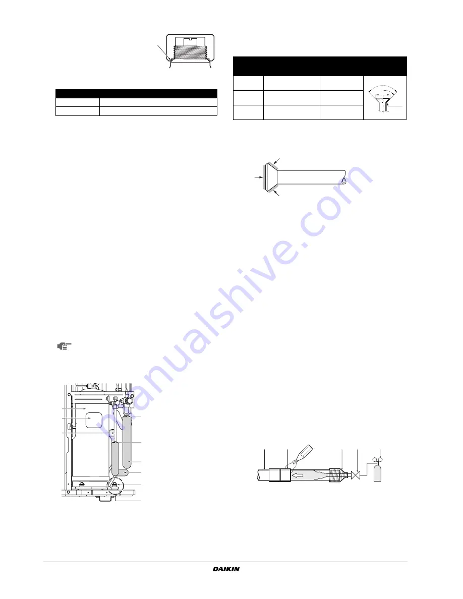
Cautions for brazing
■
Be sure to carry out a nitrogen blow when brazing.
Brazing without carrying out nitrogen replacement or releasing
nitrogen into the piping will create large quantities of oxidized
film on the inside of the pipes, adversely affecting valves and
compressors in the refrigerating system and preventing normal
operation.
■
When brazing while inserting nitrogen into the piping, nitrogen
must be set to 0.02 MPa with a pressure-reducing valve (=just
enough so that it can be felt on the skin).
1
Refrigerant piping
2
Part to be brazed
3
Taping
4
Hands valve
5
Pressure-reducing valve
6
Nitrogen
Tightening torque
Liquid pipe
13.5~16.5 N•m
Gas pipe
22.5~27.5 N•m
NOTE
Any exposed piping may cause condensation or burns
if touched.
2
1
3
5
5
A
4
4
6
1
Compressor
2
Terminal cover
3
Indoor and outdoor
field piping
4
Corking, etc.
5
Insulation material
6
Bolts
A
Be carefull with pipe,
bolt and outer panel
connections
Piping
size
Flare nut
tightening torque
A dimensions
for processing
flares (mm)
Flare shape
Ø9.5
32.7~39.9 N•m
(333~407 kgf•cm)
12.8~13.2
Ø15.9
61.8~75.4 N•m
(630~770 kgf•cm)
19.3~19.7
Ø19.1
97.2~118.6 N•m
(989.8~1208 kgf•cm)
23.6~24.0
R=0.4~0.8
45
° ±
2
90
°±
2
A
1
2
3
4
5
6
6


