background image

Operator's Guide

www.DaikinApplied.com 

IM 1005-3 • MICROTECH III REMOTE USER INTERFACE

Operator's Guide

Using the Remote User Interface

Hardware Features

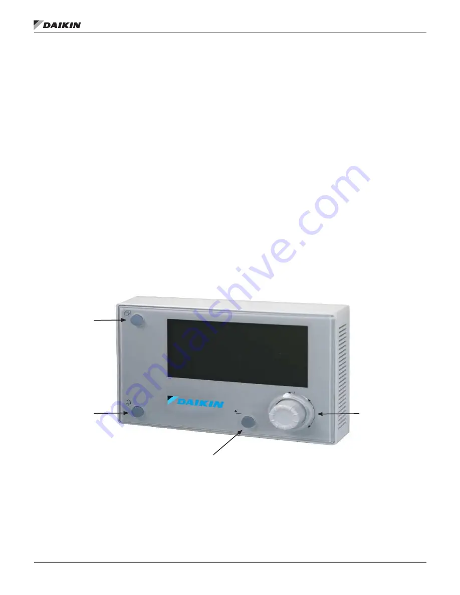
The remote user interface keypad/display consists of an 8-line 

by 30 character display, a “push and roll” navigation wheel, and 

three buttons: Alarm, Menu, and Back (

Figure 7

).

•  Turn the navigation wheel clockwise (right) or 

counterclockwise (left) to navigate between lines on a 

screen and also to increase and decrease changeable 

values when editing.  Press down on the wheel to use it 

as an Enter button.

•  Press the Back button to display the previous page.
•  Press the Home button to return to the main screen from 

the current page. 

•  Press the Alarm button to view the Alarm Lists menu.

Keypad/Display Features

The first line on each page includes the page title and the line 

number to which the cursor is currently “pointing.”  The line 

numbers are X/Y to indicate line number X of a total of Y lines 

for that page. The left most position of the title line includes an 

“up” arrow to indicate there are pages “above” the currently 

displayed items, a “down” arrow to indicate there are pages 

“below” the currently displayed items or an “up/down” arrow 

to indicate there are pages “above and below” the currently 

displayed page. Each line on a page can contain status-only 

information or include changeable data fields.  When a line 

contains status-only information and the cursor is on that line, 

all but the value field of that line is highlighted meaning the text 

is white with a black box around it.  When the line contains a 

changeable value and the cursor is at that line, the entire line is 

highlighted. 

Each line on a page may also be defined as a “jump” line, 

meaning pushing the navigation wheel will cause a “jump” to a 

new page.  An arrow is displayed to the far right of the line to 

indicate it is a “jump” line and the entire line is highlighted when 

the cursor is on that line.

NOTE: 

Only menus and items that are applicable to the 

specific unit configuration are displayed. 

Figure 7: Remote User Interface Main Features   

Home Button

Back Button

Navigation 

Wheel

Alarm Button

Summary of Contents for MicroTech III

Page 1: ...T SWP Rebel Commercial Packaged Rooftop Systems Model DPS Maverick II Commercial Packaged Rooftop Systems Models MPS Pathfinder Air Cooled Screw Chiller Models AWS AWV Trailblazer Air Cooled Scroll Co...

Page 2: ...n 5 Pre Installation 5 Location Considerations 5 Mounting Surfaces 5 Parts 5 Installation 5 Mounting 5 Wiring the Remote User Interface 7 Daisy Chain Connection 7 Direct Connection 8 Operator s Guide...

Page 3: ...nd MicroTech III from Daikin Applied Consult your local Daikin Applied representative for warranty details To find your local Daikin Applied representative go to www DaikinApplied com Hazardous Inform...

Page 4: ...onal power supply necessary Supports panel mounting and wall mounting Component Data General Figure 1 shows the details of the remote user interface hardware design The overall physical layout include...

Page 5: ...1934080031 2 Connectors using CE CE connection option 193410302 1 Note that part number 193408001 is no longer available 2 For daisy chaining unit controllers together a 2 pin connector PN 193410302 i...

Page 6: ...IM 1005 3 MICROTECH III REMOTE USER INTERFACE 6 www DaikinApplied com Installation Figure 2 Removing the Cover of remote user interface Figure 3 Wall and Surface Wiring Connections...

Page 7: ...user interface to the MicroTech III unit controller 1 Connect a twisted pair wire to the CE and CE pins of each unit controller and remote user interface see Figure 4 and Figure 5 2 Daisy chain up to...

Page 8: ...ed 3 Cycle power to the unit s once the wiring of the remote user interface is complete NOTE Power is supplied by the unit controller If a separate 24V power supply is desired please contact either th...

Page 9: ...age The left most position of the title line includes an up arrow to indicate there are pages above the currently displayed items a down arrow to indicate there are pages below the currently displayed...

Page 10: ...n multiple times or if the keypad display has been idle longer than the Password Timeout default 10 minutes The main password page provides access to enter a password access the Quick Menu view the cu...

Page 11: ...oller A status bar appears on the Downloading the Objects screen to indicate that the download is in process Figure 12 NOTE Refer to the Troubleshooting section if the remote user interface appears to...

Page 12: ...ware file POL12289 bin on the SD Card in the root directory with no other files 2 Insert the SD Card into the MicroTech III unit controller The unit controller must be powered up and running 3 Connect...

Page 13: ...ify that the unit controller has power Check wiring from the unit controller to the remote user interface NOTE Inputs and outputs are polarity sensitive Frequently Asked Questions 1 Is a separate 24V...

Page 14: ...nt to its standard terms and conditions of sale including Limited Product Warranty Consult your local Daikin Applied representative for warranty details To find your local Daikin Applied representativ...

Reviews: