Daikin MicroTech III Installation And Operation Manual Download Page 11

Operator's Guide

www.DaikinApplied.com 11 

IM 1005-3 • MICROTECH III REMOTE USER INTERFACE

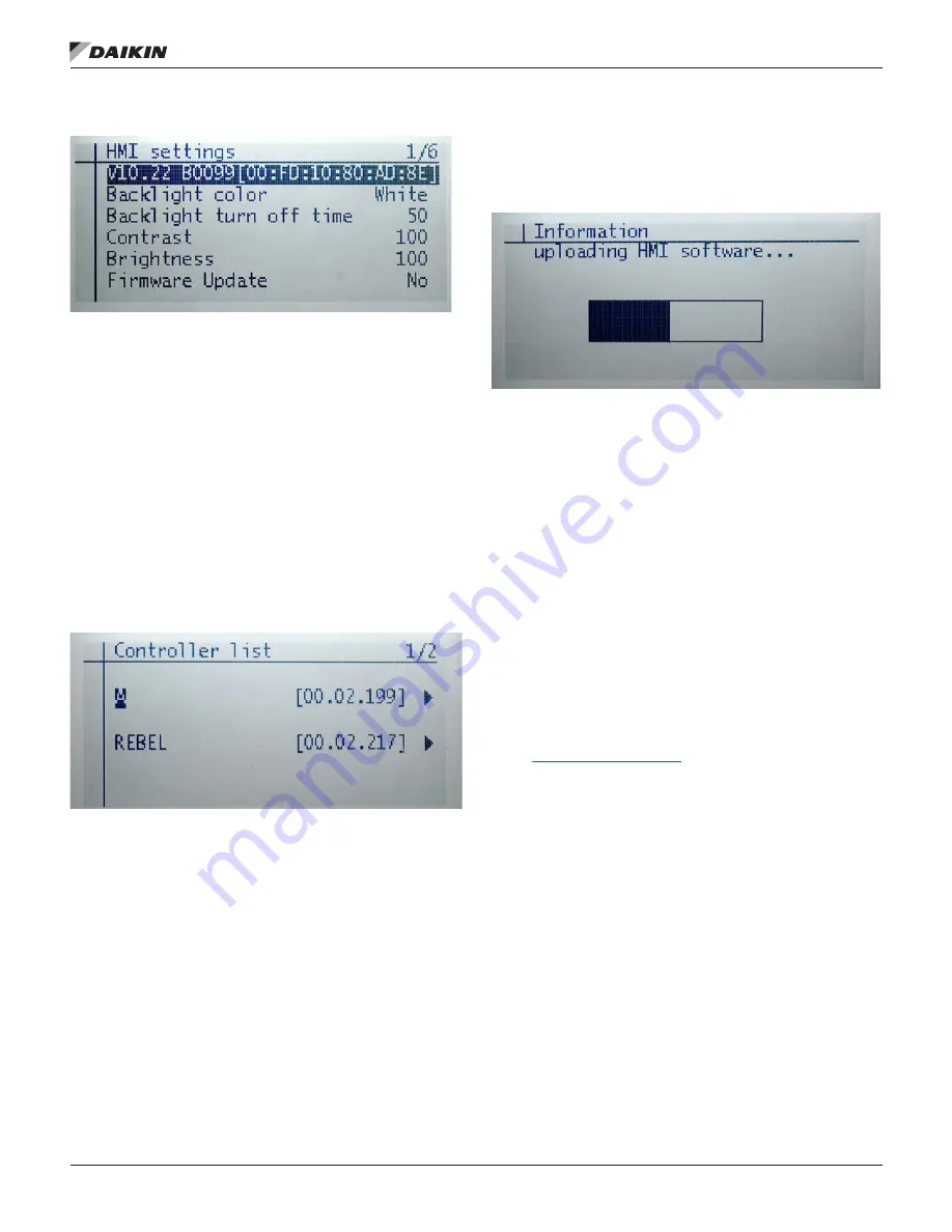
Figure 10: Main Screen HMI Settings

Synchronize with MicroTech III Unit 

Controller

1.  Press the navigation wheel to select the Controller List 

screen (

Figure 11)

.

•  The Controller List automatically updates each 

time the remote user interface is powered up so 

that information is synchronized from the main unit 

controller. 

•  The Controller List screen displays the unit 

controller(s) connected to the remote user interface.  

This screen allows the user to select between units, 

if more than one unit is connected to the remote user 

interface  

Figure 11: Controller List Details 

NOTE: 

A single unit appears on the screen as a selection 

possibility if only one unit controller is connected to 

the remote user interface.

2.  Turn the navigation wheel clockwise and then press 

down to select the desired unit.

•  The Information screen appears as the remote user 

interface performs a download sequence to import the 

necessary information from the main unit controller.  A 

status bar appears on the Downloading the Objects 

screen to indicate that the download is in process 

(Figure 12

).

NOTE: 

Refer to the Troubleshooting section if the remote 

user interface appears to "freeze" during the initial 

downloading sequence.

Figure 12: Information: Downloading Objects

3. 

Once the first unit has been downloaded, select the next 

unit controller, if applicable. The download process is 

required for each unit controller connected to the remote 

user interface.

4. 

Press the Home button for five seconds to return to the 

main screen.

NOTE: 

The Downloading the Objects sequence generally 

takes a minute or less when direct-connecting to a 

single unit.  However, the downloading sequence 

takes longer when using the daisy-chain connection.
When the download sequence is complete, the Main 

screen of the unit controller appears on the remote 

user interface. At this point, the remote user interface 

and unit controller are synchronized.

5.  Access and adjust the same parameters that are 

available via the unit controller keypad/display.  Refer 

to the applicable MicroTech III unit controller Operation 

Manual for the keypad menu structure and detailed 

description the unit controller sequence of operation 

(

www.DaikinApplied.com

).

Summary of Contents for MicroTech III

Page 1: ...T SWP Rebel Commercial Packaged Rooftop Systems Model DPS Maverick II Commercial Packaged Rooftop Systems Models MPS Pathfinder Air Cooled Screw Chiller Models AWS AWV Trailblazer Air Cooled Scroll Co...

Page 2: ...n 5 Pre Installation 5 Location Considerations 5 Mounting Surfaces 5 Parts 5 Installation 5 Mounting 5 Wiring the Remote User Interface 7 Daisy Chain Connection 7 Direct Connection 8 Operator s Guide...

Page 3: ...nd MicroTech III from Daikin Applied Consult your local Daikin Applied representative for warranty details To find your local Daikin Applied representative go to www DaikinApplied com Hazardous Inform...

Page 4: ...onal power supply necessary Supports panel mounting and wall mounting Component Data General Figure 1 shows the details of the remote user interface hardware design The overall physical layout include...

Page 5: ...1934080031 2 Connectors using CE CE connection option 193410302 1 Note that part number 193408001 is no longer available 2 For daisy chaining unit controllers together a 2 pin connector PN 193410302 i...

Page 6: ...IM 1005 3 MICROTECH III REMOTE USER INTERFACE 6 www DaikinApplied com Installation Figure 2 Removing the Cover of remote user interface Figure 3 Wall and Surface Wiring Connections...

Page 7: ...user interface to the MicroTech III unit controller 1 Connect a twisted pair wire to the CE and CE pins of each unit controller and remote user interface see Figure 4 and Figure 5 2 Daisy chain up to...

Page 8: ...ed 3 Cycle power to the unit s once the wiring of the remote user interface is complete NOTE Power is supplied by the unit controller If a separate 24V power supply is desired please contact either th...

Page 9: ...age The left most position of the title line includes an up arrow to indicate there are pages above the currently displayed items a down arrow to indicate there are pages below the currently displayed...

Page 10: ...n multiple times or if the keypad display has been idle longer than the Password Timeout default 10 minutes The main password page provides access to enter a password access the Quick Menu view the cu...

Page 11: ...oller A status bar appears on the Downloading the Objects screen to indicate that the download is in process Figure 12 NOTE Refer to the Troubleshooting section if the remote user interface appears to...

Page 12: ...ware file POL12289 bin on the SD Card in the root directory with no other files 2 Insert the SD Card into the MicroTech III unit controller The unit controller must be powered up and running 3 Connect...

Page 13: ...ify that the unit controller has power Check wiring from the unit controller to the remote user interface NOTE Inputs and outputs are polarity sensitive Frequently Asked Questions 1 Is a separate 24V...

Page 14: ...nt to its standard terms and conditions of sale including Limited Product Warranty Consult your local Daikin Applied representative for warranty details To find your local Daikin Applied representativ...

Reviews: