Unit Controller
www.DaikinApplied.com 49
IOM 1322-1 • WATER-COOLED SCROLL COMPRESSOR
to work through the matrix hierarchy. From any menu screen,
pressing the MENU key will take you to the top level of the
hierarchy. The display will show ALARM, VIEW, and SET as
shown in Figure 8. This corresponds to the second row of
screens on Figure 10. One of these groups of screens can then
be selected by pressing the key connected to it via the pathway
shown in Figure 8 on page 18.
For example, selecting
ALARM
will go the next row of menus
under
ALARM (ALARM LOG or ACTIVE ALARM)
. Selecting
VIEW will go the next level of screens under
VIEW (VIEW
UNIT STATUS or VIEW UNIT TEMP) .
Selecting
SET
will go to
a series of screens for looking at and changing set points.
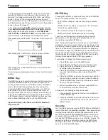
After pressing the MENU button, the top-level menu screen will
show:
After pressing the “VIEW” button, a menu screen will show:
After pressing the “EVAPORATOR” button, the selected data
screen will show:
The arrow keys will automatically return to the “scroll” mode at
this time.
MENU Key
The MENU key is used to switch between the shortcut method
(known as the MENU mode and as shown in Figure 8) and
scrolling method (known as the SCROLL mode). The MENU
mode is the shortcut to specific groups of menus used for
checking ALARMS, for VIEWING information, or to SET set
point values. The SCROLL mode allows the user to move
about the matrix (from one menu to another, one at a time) by
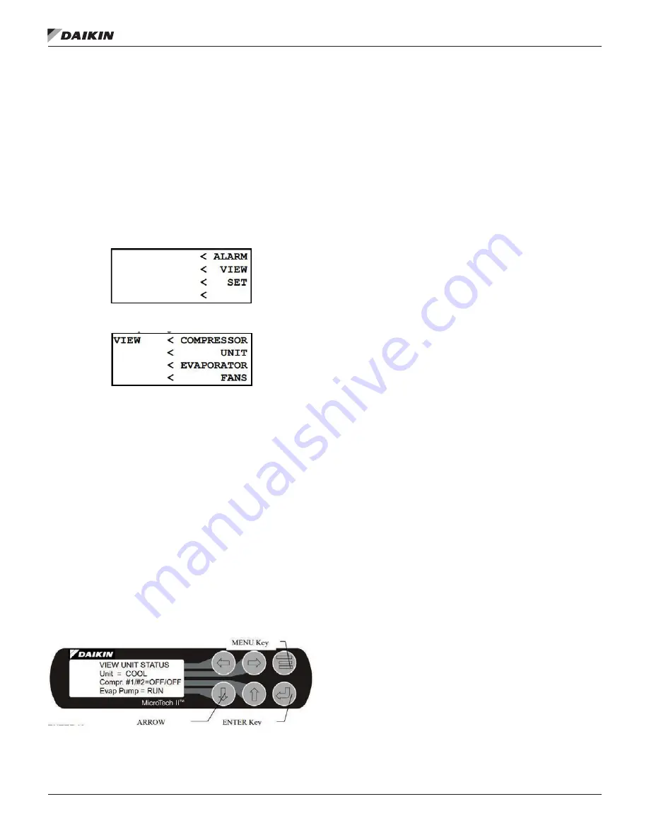
using the four ARROW keys. A typical menu screen is shown
in the following figure. Pressing the MENU key from any menu
screen will automatically return you to the MENU mode.
Figure 24: Display in the Shortcut (SCROLL) Mode and
Keypad Layout
ENTER Key
Pressing the ENTER key changes the function of the ARROW
keys to the editing function as shown below:
LEFT: Default, changes a value to the factory-set default
value.
RIGHT: Cancel, cancels any change made to a value and
returns to the original setting.
UP: Increment, increases the value of the setting
DOWN: Decrement decreases the value of a setting.
These four edit functions are indicated by one-character
abbreviation on the right side of the display (this mode is
entered by pressing the ENTER key).
Most menus containing set point values have several different
set points shown on one menu. When in a set point menu, the
ENTER key is used to proceed from the top line to the second
line and on downward. The cursor will blink at the entry point
for making a change. The ARROW keys (now in the edit mode)
are used to change the set point as described above. When
the change has been made, press the ENTER key to enter it.
Nothing is changed until the ENTER key is pressed.
For example, to change the chilled water set point:
1. Press MENU key to go to the MENU mode.
2.
Press SET (the UP Key) to go to the set point menus.
3. Press UNIT SPs (the Right key) to go to set points
associated with unit operation.
4. Press the DOWN key to scroll down through the set point
menus to the third menu which contains Evap LWT=
XX.X°F.
5. Press the ENTER key to move the cursor down from the
top line to the second line in order to make the change.
6. Use the ARROW keys (now in the edit mode as shown
above) to change the setting.
7. When the desired value is achieved, press ENTER to
enter it and also move the cursor down.
At this point, the following actions can be taken:
1. Change another set point in this menu by scrolling to it
with the ENTER key.
2.
Using the ENTER key, scroll to the first line in the menu.
From there the ARROW keys can be used to scroll to
different menus.
Security
Two four-digit passwords provide OPERATOR and MANAGER
levels of access to changeable parameters. The passwords are
pre-programmed into the controller. Either password can be
entered using the ENTER PASSWORD screen which can be
accessed either through the SET OTHER menu or by simply
pressing the ENTER key while on one of the SET screens. The
password can then be entered by pressing the ENTER key,
scrolling to the correct value with the UP and DOWN arrow
keys, and pressing ENTER again.
Summary of Contents for IOM 1322-1
Page 4: ......
Page 57: ...Unit Controller Operation www DaikinApplied com 57 IOM 1322 1 WATER COOLED SCROLL COMPRESSOR...
Page 71: ...Unit Maintenance www DaikinApplied com 71 IOM 1322 1 WATER COOLED SCROLL COMPRESSOR...
Page 74: ...IOM 1322 1 WATER COOLED SCROLL COMPRESSOR 74 www DaikinApplied com Troubleshooting Chart...
Page 75: ...Troubleshooting Chart www DaikinApplied com 75 IOM 1322 1 WATER COOLED SCROLL COMPRESSOR...
Page 76: ...IOM 1322 1 WATER COOLED SCROLL COMPRESSOR 76 www DaikinApplied com Troubleshooting Chart...
Page 77: ...Troubleshooting Chart www DaikinApplied com 77 IOM 1322 1 WATER COOLED SCROLL COMPRESSOR...
Page 78: ...IOM 1322 1 WATER COOLED SCROLL COMPRESSOR 78 www DaikinApplied com Troubleshooting Chart...

