IOM 1322-1 • WATER-COOLED SCROLL COMPRESSOR 40 www.DaikinApplied.com
Unit Controller
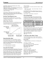
Pull Down Rate
The slope value calculated above will be a negative value as
the water temperature is dropping. For use in some control
functions, the negative slope is converted to a positive value by
multiplying by –1.
Evaporator Saturated Temperature
Evaporator saturated temperature is calculated from the
evaporator pressure for each circuit.
R410A Evaporator Saturated Temperatures
When R410A refrigerant is selected the refrigerant pressure
will be fitted to a curve made up of 24 straight-line segments.
The accuracy of calculated saturated temperatures are less
than +/- 0.5°F when compared to standard look up tables for
R410A.
R134a Evaporator Saturated Temperatures (Templifiers
only)
When R134a refrigerant is selected the refrigerant pressure
will be fitted to a curve made up of 12 straight-line segments.
The accuracy of calculated saturated temperatures is +/-
0.5º F when compared to standard look up tables for R134a
refrigerant.
Condenser Saturated Temperature
Condenser saturated temperature shall be calculated from the
condenser pressure for each circuit.
R410A Evaporator Saturated Temperatures
When R410A refrigerant is selected the refrigerant pressure
will be fitted to a curve made up of 24 straight-line segments.
The accuracy of calculated saturated temperatures are less
than +/- 0.5°F when compared to standard look up tables for
R410A.
R134a Evaporator Saturated Temperatures (Templifiers
only)
When R134a refrigerant is selected the refrigerant pressure
will be fitted to a curve made up of 12 straight-line segments.
The accuracy of calculated saturated temperatures is +/-
0.5º F when compared to standard look up tables for R134a
refrigerant.
Evaporator Approach
The evaporator approach is calculated for each circuit.
For R134a and R410A refrigerant the equation is:
Evaporator Approach = LWT – Evaporator Saturated
Temperature
Suction Superheat
Suction superheat is calculated for each circuit using the
following equation:
Suction superheat = Suction Temperature – Evaporator
Saturated Temperature
Pump Down Pressure
The pressure to which a circuit will pump down is based on the
Low Evaporator Pressure Unload set point. The equation is as
follows:
Pumpdown pressure = Low evap pressure unload – 15 psi
The low limit for the calculated Pumpdown Pressure set point
is 10.0 psi
Unit Enable
The Unit Enable Set Point controls enabling and disabling the
unit. The Unit Enable Set Point has options of OFF and ON.
The Unit OFF input, Remote input, keypad entry, and BAS
request can alter this set point. The Control Source Set Point
determines which sources can change the Unit Enable Set
Point with options of SWITCHES, KEYPAD or NETWORK.
Changing the Unit Enable Set Point is accomplished according
to the following table.
NOTE:
An “x” indicates that the value is ignored.
Unit Off
Input
Control Source
Set Point
Remote
Input
Keypad
Entry
BAS
Request
Unit
Enable
OFF
X
X
X
X
OFF
X
SWITCHES
OFF
X
X
OFF
ON
SWITCHES
ON
X
X
ON
ON
KEYPAD
X
OFF
X
OFF
ON
KEYPAD
X
ON
X
ON
ON
NETWORK
X
X
OFF
OFF
ON
NETWORK
OFF
X
X
OFF
ON
NETWORK
ON
X
ON
ON
Unit Mode
The overall operating mode of the chiller is set by the Unit
Mode Set Point with options of COOL, COOL w/Glycol, ICE w/
Glycol, and TEST. This set point can be altered by the keypad,
BAS, and Mode input.
Changes to the Unit Mode Set Point are controlled by two
additional set points.
• Available Modes Set Point: Determines the operational
modes available at any time with options of COOL, COOL
w/Glycol, COOL/ICE w/Glycol, ICE w/Glycol and TEST
• Control Source Set Point: Determines the source that can
change the Unit Mode Set Point with options of KEYPAD,
NETWORK, or SWITCHES.
When the Control source is set to KEYPAD, the Unit Mode
shall stay at its previous setting until changed by the operator.
When the Control source is set to BAS, the most recent BAS
mode request shall go into effect even if it changed while the
Control source was set to KEYPAD or DIGITAL INPUTS.
Changing the Unit Mode Set Point can be accomplished
according to the following table.
NOTE:
An “x” indicates that the value is ignored.
Summary of Contents for IOM 1322-1
Page 4: ......
Page 57: ...Unit Controller Operation www DaikinApplied com 57 IOM 1322 1 WATER COOLED SCROLL COMPRESSOR...
Page 71: ...Unit Maintenance www DaikinApplied com 71 IOM 1322 1 WATER COOLED SCROLL COMPRESSOR...
Page 74: ...IOM 1322 1 WATER COOLED SCROLL COMPRESSOR 74 www DaikinApplied com Troubleshooting Chart...
Page 75: ...Troubleshooting Chart www DaikinApplied com 75 IOM 1322 1 WATER COOLED SCROLL COMPRESSOR...
Page 76: ...IOM 1322 1 WATER COOLED SCROLL COMPRESSOR 76 www DaikinApplied com Troubleshooting Chart...
Page 77: ...Troubleshooting Chart www DaikinApplied com 77 IOM 1322 1 WATER COOLED SCROLL COMPRESSOR...
Page 78: ...IOM 1322 1 WATER COOLED SCROLL COMPRESSOR 78 www DaikinApplied com Troubleshooting Chart...


