


FXFQ20~125M8V3B
VRV System air conditioners
4PW25082-1A
Installation and operation manual
4
■
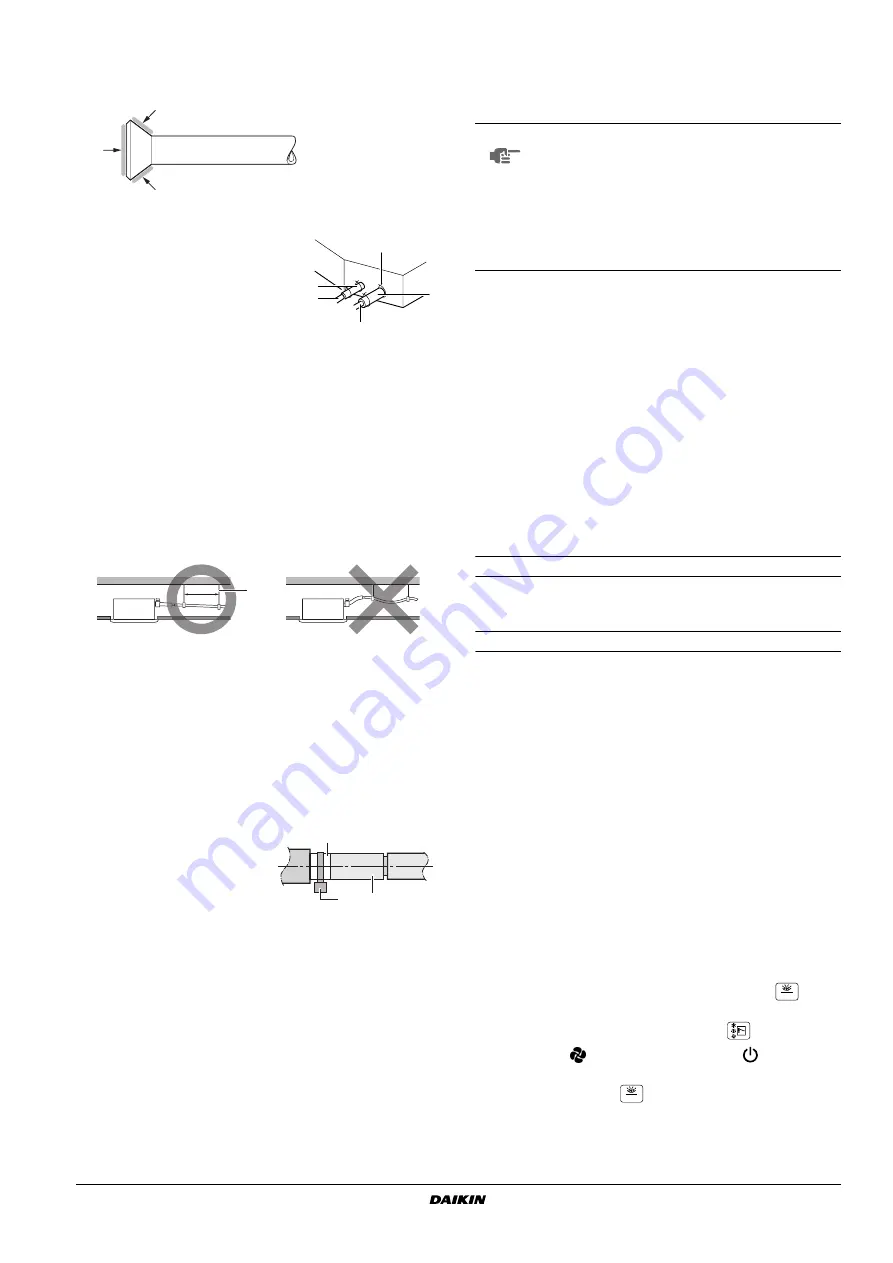
When connecting the flare nut, coat the flare both inside and
outside with ether oil or ester oil and initially tighten by hand 3 or
4 turns before tightening firmly.
Coat here with ether oil or ester oil
■
Check the pipe connector for gas leaks, then insulate it as
shown in the figure below.
■
If the refrigerant gas leaks during the work, ventilate the area. A
toxic gas is emitted by the refrigerant gas being exposed to a fire.
■
Finally make sure there is no refrigerant gas leak. A toxic gas
may be released by the refrigerant gas leaking indoor and being
exposed to flames from an area heater, cooking stove, etc.
D
RAIN
PIPING
WORK
Rig the drain piping as shown in figure and take measures against
condensation. Improperly rigged piping could lead to leaks and
eventually wet furniture and belongings.
1.
Install the drain pipes.
•
Keep piping as short as possible and slope it downwards so that
air may not remain trapped inside the pipe.
•
Keep pipe size equal to or greater than that of the connecting
pipe (Vinyl pipe of 25 mm nominal diameter and 32 mm outer
diameter).
•
Insert the supplied drain hose into the drain socket, up to the
white tape.
•
Tighten the clamp until the screw head is less then 4 mm from the
hose.
•
Insulate the drain hose inside the building.
•
If the drain hose cannot be sufficiently set on a slope, fit the hose
with drain raising piping (field supply).
How to perform piping
1
Connect the drain hose to the drain raising pipes, and insulate
them.
2
Connect the drain hose to the drain outlet on the indoor unit, and
tighten it with the clamp.
Precautions
■
Install the drain raising pipes at a height of less than 550 mm.
■
Install the drain raising pipes at a right angle to the indoor unit
and no more than 300 mm from the unit.
2.
After piping work is finished, check if drainage flows
smoothly.
•
Open the water inlet lid, add approximately 2 l of water gradually
and check the drainage flow.
Method of adding water. See
When electric wiring work is finished
Check drainage flow during COOL running, explained in chapter
"
When electric wiring work is not finished
■
Remove the switch box lid and connect the power supply and
remote controller to the terminals.
See
•
Next, press the inspection/test operation button
on the
remote controller. The unit will engage the test operation mode.
Press the operation mode selector button
until selecting fan
operation
. Then, press the on/off button
. The indoor unit
fan and drain pump will start up. Check that the water has drained
from the unit. Press
to go back to the first mode.
1
Liquid pipe
2
Gas pipe
3
Insulation for fitting of liquid line
(supplied with the unit)
4
Insulation for fitting of gas line (sup-
plied with the unit)
5
Clamps
(use 2 clamps per insulation)
1
Hanging bar
1
Clamp metal (supplied with
the unit)
2
Drain hose (supplied with
the unit)
3
White tape (field supply)
1
Ceiling slab
2
Hanger bracket
3
Adjustable range
4
Drain raising pipe
5
Drain hose (supplied with the unit)
6
Clamp metal (supplied with the unit)
5
4
2
1
3
1-1.5 m
1
2
1
3
NOTE
■
The incline of attached drain hose should be
75 mm or less so that the drain socket does not
have to stand additional force.
■
To ensure a downward slope of 1:100, install
hanging bars every 1 to 1.5 m.
■
If unifying multiple drain pipes, install the pipes as
shown in
. Select converging drain pipes
whose gauge is suitable for the operating capacity
of the unit.
1
T-joint converging drain pipes
1
Portable pump
2
Drain pipe
3
Service cover
4
Inspection opening
5
Service drain outlet (with rubber plug) (Use this outlet to drain
water from the drain pan)
6
Plastic watering can (Tube should be about 100 mm long.)
(Adding water through air discharge outlet)
7
Bucket (Adding water from inspection opening)
1
Switch box lid (1)
2
Power supply
3
Power supply terminal board
4
Rubber bush A
5
Clamp A
6
Switch box lid (2) with wiring diagram label
7
Transmission wiring
8
Terminal board for transmission wiring
9
Rubber bush B
10
Clamp B
11
Outside of the unit
12
Inside of the unit
13
Cable (power supply or transmission wiring)
14
Opening for the cable
15
Small sealing (supplied with the unit)
TEST
TEST


