


8
NOTE
• Apply ester oil or ether oil around the flare portions before
connecting.
• The flare nuts used must be those included with the main
body.
• Over-tightening may damage the flare and cause a refriger-
ant leakage.
Not recommendable but in case of emergency
You must use a torque wrench but if you are obliged to
install the unit without a torque wrench, you may
follow the installation method mentioned below.
After the work is finished, make sure to check that
there is no gas leak.
When you keep on tightening the flare nut with a spanner,
there is a point where the tightening torque
suddenly increases. From that position, further tighten the
flare nut the angle shown below:
Table 4
7-3
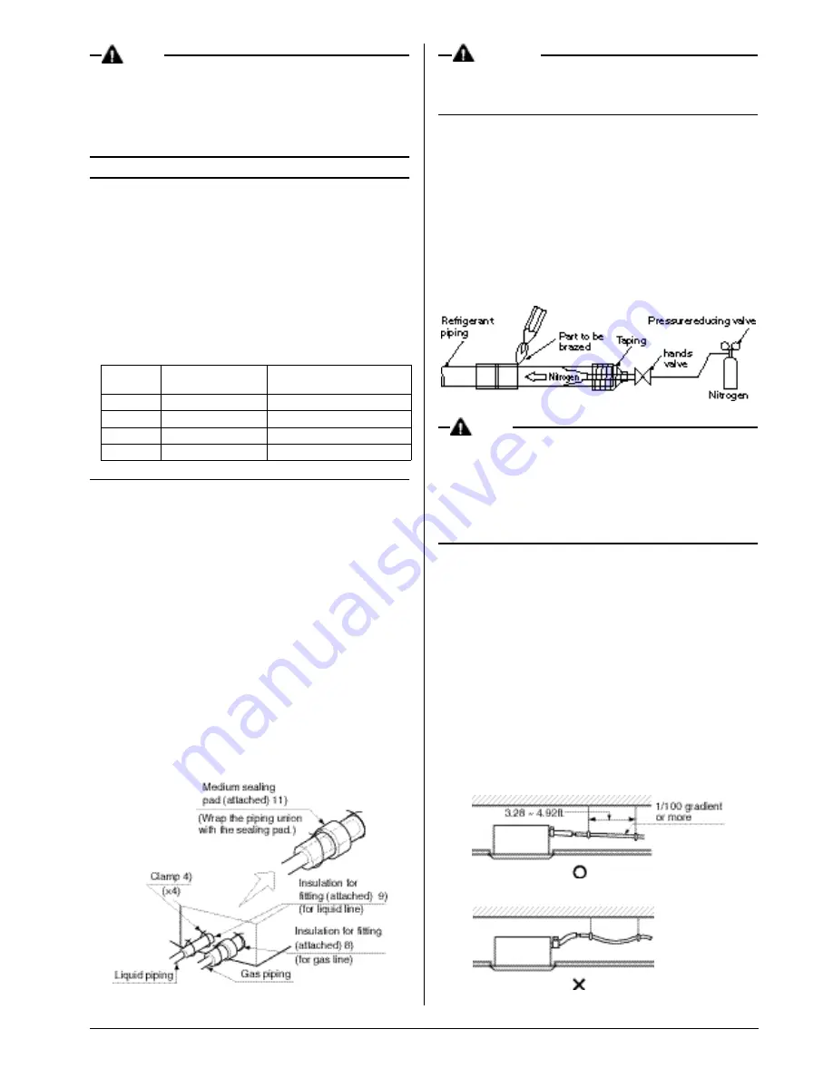
Piping insulation
• Execute heat insulation work completely on both sides of the
gas piping and the liquid piping. Otherwise, a water leakage
can result sometimes.
• When using a heat pump, the temperature of the gas piping
can reach up to approximately 250°F, so use insulation
which is sufficiently resistant.
• Also, in cases where the temperature and humidity of the refrig-
erant piping sections might exceed 86°F or RH80%, reinforce
the refrigerant insulation. (13/16” or thicker) Condensation may
form on the surface of the insulating material.
• Check the pipe connector for gas leaks, then insulate it as
shown in the drawing below.
• Make absolutely sure to execute heat insulation works on the
pipe-connecting section after checking gas leakage by thor-
oughly studying the following figure and using the attached
heat insulating materials for fitting. (Fasten both ends with
the clamps (accessory).)
• Wrap the sealing pad (accessory) only around the insulation
for the joints on the gas piping side.
CAUTION
Be sure to insulate any field piping all the way to the piping
connection inside the unit. Any exposed piping may cause
condensation or burns if touched.
7-4
Brazing referigerant piping
• Before brazing local refrigerant piping, nitrogen gas shall be
blown through the piping to expel air from the piping.
If your brazing is done without nitrogen gas blowing, a large
amount of oxide film develops inside the piping, and could
cause system malfunction.
• When brazing the refrigerant piping, only begin brazing after
having carried out nitrogen substitution or while inserting
nitrogen into the refrigerant piping. Once this is done, con-
nect the indoor unit with a flared or a flanged connection.
• Nitrogen should be set to 2.9psi. with a pressure-reducing
valve if brazing while inserting nitrogen into the piping.
NOTE
Do not use flux when brazing refrigerant piping. Therefore,
use the phosphor copper brazing filter metal (BCuP) which
does not require flux.
(Flux has extremely harmful infulence on refrigerant piping
sysems. For instance, if the chlorine based flux is used, it
will cause pipe corrosion or, in particular, if the flux contains
fluorine, it will damage the refrigerant oil.)
8. DRAIN PIPING WORK
〈〈
Rig the drain pipe as shown below and take measures
against condensation. Improperly rigged piping could lead
to leaks and eventually wet furniture and belongings.
〉〉
(1) Rig drain piping
• The diameter of the drain pipe should be greater than or
equal to the diameter of the connecting pipe (vinyl tube; pipe
size: 1”; outer dimension: 1 1/4”). (This does not apply to
rises.)
• Keep the drain pipe short and sloping downwards at a gradi-
ent of at least 1/100 to prevent air pockets from forming.
• If the drain hose cannot be sufficiently set on a slope, exe-
cute the drain raising piping.
• To keep the drain hose from sagging, space hanging wires
every 3.28 ~ 4.92ft .
Pipe size
Further tightening
angle
Recommended arm length of
tool (in.)
φ
1/4”
60 to 90 degrees
Approx. 5 7/8
φ
3/8”
60 to 90 degrees
Approx. 7 7/8
φ
1/2”
30 to 60 degrees
Approx. 9 13/16
φ
5/8”
30 to 60 degrees
Approx. 11 13/16
Summary of Contents for FXFQ12MVJU
Page 15: ...14 MEMO...


