background image

English 

8

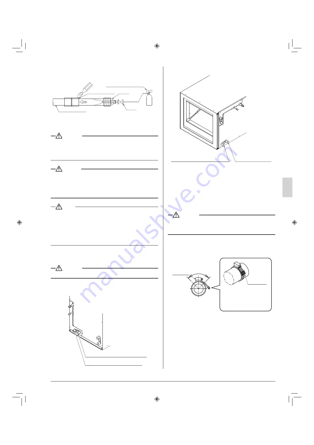
When brazing the refrigerant piping, perform nitrogen re-

• 

placement fi rst, or perform the brazing while feeding nitro-
gen into the refrigerant piping. 

(Refer to Fig. 6)

Refrigerant piping

Part to be brazed

Taping

Pressure-reducing valve

hands 
valve

Nitrogen

Nitrogen

Fig. 6

 CAUTION

When brazing piping while feeding nitrogen inside the 


piping, make sure to set the nitrogen pressure to 2.9 psi or 
less using the pressure reducing valve.
(This pressure is such that a breeze is blown to your cheek.)

 DANGER

Use of oxygen could result in an explosion resulting in 

• 

serious injury or death. Only use dry nitrogen gas.
Refrigerant gas may produce toxic gas if it comes in contact 


with fi re such as from a fan heater, stove or cooking device. 
Exposure to this gas could cause severe injury or death.

 NOTE

Do not use fl ux when brazing refrigerant piping. Therefore, 


use the phosphor copper brazing fi ller metal (BCuP) which 
does not require fl ux.
Flux has an extremely negative effect on refrigerant piping 
systems. For instance, if chlorine based fl ux is used, it will 
cause piping corrosion. Flux containing fl uorine will damage 
refrigerant oil.

DRAIN PIPING WORK

6. 

 CAUTION

Make sure all water is out before making the duct connection.


Install drain piping as described Fig. 7.

(1) 

Secondary drain piping connection hole

Primary drain piping connection hole

In case of vertical installation

Fig. 7-1

Primary drain piping connection hole

Secondary drain piping 
connection hole

In case of horizontal installation

Fig. 7-2

Perform drain work so that the unit is drained thoroughly. 

• 

(Be sure to insulate the following 2 locations since 
condensation may cause water leakage.)
Be sure to use the included Drain hose (5) and Metal 

• 

clamp (4).

Insert the Drain hose (5) up to the step on the drain 
socket. Within the range of the tape section at the 
end of the inserted hose, tighten the Metal clamp (4) 
to the torques of 0.99 ± 0.1 lbf·ft (11.9 ± 1.2 lbf·in).

 CAUTION

Do not tighten the Metal clamp (4) to torques exceeding the 


specifi cation. Otherwise, the Drain hose (5), the socket, and 
the Metal clamp (4) may become damaged.

To avoid the Sealing pad (large) (9) from tearing at the 

• 

edge of the Metal clamp (4), either affi x a plastic tape 
on the edge of the Metal clamp (4) or bend the end of 
the Metal clamp (4) inward as shown in the fi gure.

Plastic tape

To avoid tearing the Sealing 
pad (large) (9), affix a 
plastic tape.

Tightening 
section

Approx. 90°

<When affixing plastic tape>

Cross section A-A 

01_EN_3P250363-4C.indd   8

01_EN_3P250363-4C.indd   8

12/28/2011   11:51:50 AM

12/28/2011   11:51:50 AM

Summary of Contents for FTQ18PBVJU

Page 1: ...with the equipment owner Lire soigneusement ces instructions avant l installation Conserver ce manuel port e de main pour r f rence ult rieure Ce manuel doit tre donn au propri taire de l quipement Le...

Page 2: ...installation ventilate the area immediately Refrigerant gas may produce toxic gas if it comes in contact with fire Exposure to this gas could cause severe injury or death After completing the install...

Page 3: ...ant pipes may be hot or cold depending on the condition of the refrigerant flowing through the refrigerant piping compressor and other refrigerant cycle parts Your hands may suffer burns or frostbite...

Page 4: ...t an air filter part to be procured in the field in the suction air passage in order to prevent water leaking etc The accessories needed for installation must be retained in your custody until the ins...

Page 5: ...ual along with the installation manual to the customer Did you explain the customer the handling and cleaning methods of the field supplies e g the air filter air inlet grilles and air outlet grille D...

Page 6: ...art type the remote controller s transmission distance may be short ened Indoor units should be installed as far away from fluorescent lighting as possible DANGER Do not install unit in an area where...

Page 7: ...burns And be sure to use the insulation which can withstand such temperatures of 248 F or more for the gas piping Reinforce the insulation on the refrigerant piping accord ing to the installation env...

Page 8: ...cks Refer to Fig 5 Heat insulation procedure for gas piping Insulation material for piping on unit side Insulation material for piping field supply Make sure that the seam faces upward Clamp material...

Page 9: ...sure all water is out before making the duct connection Install drain piping as described Fig 7 1 Secondary drain piping connection hole Primary drain piping connection hole In case of vertical insta...

Page 10: ...in the manner described below INSTALLING THE DUCT 7 Exercise care regarding the following when performing duct work Verify that duct work does not exceed the unit s setting range of external static pr...

Page 11: ...1 8 36 type 2 8 2 2 42 type 3 6 400 2 8 MCA Minimum Circuit Amps A MOP Max Overcurrent Protective Device A HP Fan motor output W FLA Full Load Amps A WIRING EXAMPLE 9 HOW TO CONNECT WIRINGS 9 1 Preca...

Page 12: ...wiring and transmission wires to the terminal block shown in Fig 8 Then secure them in place with the included Clamp material 1 as shown in Fig 8 to protect them from external force from outside the...

Page 13: ...neat and does not cause the electric front panel to stick up then close the panel firmly When attaching the front panel make sure you do not pinch any wires Outside the air conditioners separate the l...

Page 14: ...mote controller 2 SUB Remote controller 1 MAIN 1 P 2 P 1 F 2 F 1 T 2 T FORCED OFF REMOTE CONTRL TRANSMISSION WIRING REMOTE CONTROL FORCED OFF AND ON 9 3 OFF OPERATION Connect input lines from the outs...

Page 15: ...rohibited Unit operated by changing input A from off to on Input A off to allow remote controller Unit stopped by changing input A from on to off SETTING THE FILTER SIGN DISPLAY INTERVAL 10 3 Explain...

Page 16: ...the wires to the terminal block 10P of the product The terminal Nos for wire connection are shown below Refer to the information as needed Terminal Nos are indicated on the name plate for the termina...

Page 17: ...the wiring was done incorrectly or that the power is not on so check again Remote controller display Contents A8 lit Error in power supply voltage to indoor unit C1 lit Fan driver PCB of indoor unit...

Page 18: ...363 4C EM11A011 1201 HT 1645 Wallace Drive Suite 110 Carrollton TX 75006 USA info daikinac com www daikinac com 00_CV_3P250363 4C indd 2 00_CV_3P250363 4C indd 2 11 18 2011 9 10 36 PM 11 18 2011 9 10...

Reviews: