ESIE10-01
General Outline
1–93
3
1
4
5
Control circuit:
Every machine of the series is supplied with an auxiliary 400/115 V control circuit transformer. No
additional cable for the control system power supply is thus required. Only if the optional separate
accumulation tank is requested, the electrical antifreeze resistance must have a separate power
supply.
Electrical heaters
The machine has an antifreeze electrical heater installed directly on the evaporator. Each circuit also
has an electrical heater installed in the compressor, whose purpose is to keep the oil warm thus
preventing the presence of liquid refrigerant mixed with the oil in the compressor. Clearly, the
operation of electrical heaters is guaranteed only if there is a constant power supply. If it is not possible
to keep the machine powered when inactive during winter, apply at least two of the procedures
described in the 'Mechanical installation' section under the 'antifreeze protection of evaporator and
exchangers', and power the machine at least 24 hours prior to compressor start-up in order to allow
the oil to warm up.
Pump electrical
supply
On request, the machine can be fitted with a fully-wired pump kit controlled by the machine
microprocessor. In this case, no further checks are required. Should the system use pumps outside
the machine (not supplied with the unit), fit the supply line for each pump with a thermal-magnetic
circuit breaker and a command contact.
Water pump control
Connect the control contactor coil power supply to terminals 27 and 28 (pump #1) and 48 and 49
(pump 2) located on terminal board M5, and install the contactor on a power supply with the same
voltage as the pump contactor coil. The terminals are connected to a clean microprocessor contact.
The microprocessor contact has the following commutation capacity:
Q
Maximum voltage:
250 V AC
Q
Maximum current:
2 A Resistive - 2 A Inductive
Q
Reference standard:
EN 60730-1
The wiring described above allows the microprocessor to manage the water pump automatically. It is
good practice to install a clean status contact pump's thermal-magnetic circuit breaker and to connect
it in series with the flow switch.
Alarm relays -
Electrical wiring
The unit has a clean-contact digital output that changes state whenever an alarm occurs in one of the
refrigerant circuits. Connect this signal to an external visual or sound alarm, or to the BMS, in order to
monitor its operation. See the machine's wiring diagram for wiring.
Unit on/off remote
control - Electrical
wiring
The machine has a digital input that allows remote control. A start-up timer, a circuit breaker or a BMS
can be connected to this input. Once the contact has been closed, the microprocessor launches the
start-up sequence by first turning on the water pump and then the compressors. When the contact is
opened, the microprocessor launches the machine shutdown sequence. The contact must be clean.
Double setpoint -
Electrical wiring
The double setpoint function uses a switch to allow for to change over the unit setpoint between two
predefined values in the unit controller. An example of an application is ice production during the night
and standard operation during the day. Connect a circuit breaker or timer between terminals 20 and
21 and terminal board M5. The contact must be clean.
External water
setpoint reset -
Electrical wiring
(optional)
The machine's local setpoint can be modified by means of an external analogue 4-20 mA signal. Once
this function has been enabled, the microprocessor allows for the modification of the setpoint from the
set local value up to a differential of 3°C max. 4 [mA] corresponds to a 0 [°C] reset, 20 [mA]
corresponds to the setpoint plus maximum differential. The signal cable must be directly connected to
terminals 35 and 36 of the M5 terminal board. The signal cable must be of the shielded type and must
not be laid in the vicinity of the power cables, so as not to induce interference with the electronic
controller.
Summary of Contents for EWAD620-C17C-SS
Page 2: ......
Page 8: ...ESIE10 01 1 2 Part 1 System Outline 3 1 1 5...
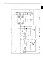
Page 111: ...ESIE10 01 General Outline Part 1 System Outline 1 105 3 1 4 5 1 36 1 Power Compressor 1 2...
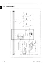
Page 112: ...General Outline ESIE10 01 1 106 Part 1 System Outline 3 1 1 4 5 1 36 2 Power Compressor 3...
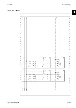
Page 113: ...ESIE10 01 General Outline Part 1 System Outline 1 107 3 1 4 5 1 36 3 Kit Pumps...
Page 122: ...General Outline ESIE10 01 1 116 Part 1 System Outline 3 1 1 4 5 1 36 12 Digital Inputs Board...
Page 123: ...ESIE10 01 General Outline Part 1 System Outline 1 117 3 1 4 5 1 36 13 Digital Outputs Board...
Page 124: ...General Outline ESIE10 01 1 118 Part 1 System Outline 3 1 1 4 5 1 36 14 Digital Outputs Board...
Page 127: ...ESIE10 01 General Outline Part 1 System Outline 1 121 3 1 4 5 1 36 17 Extension Control Fans 4...
Page 131: ...ESIE10 01 General Outline Part 1 System Outline 1 125 3 1 4 5 1 36 21 EEXV Compressor 1...
Page 134: ...General Outline ESIE10 01 1 128 Part 1 System Outline 3 1 1 4 5 1 36 24 EEXV Compressor 2...
Page 137: ...ESIE10 01 General Outline Part 1 System Outline 1 131 3 1 4 5 1 36 27 EEXV Compressor 3...
Page 138: ...General Outline ESIE10 01 1 132 Part 1 System Outline 3 1 1 4 5 1 36 28 Pumps Control...
Page 139: ...ESIE10 01 General Outline Part 1 System Outline 1 133 3 1 4 5 1 36 29 Terminals M1 M2...
Page 140: ...General Outline ESIE10 01 1 134 Part 1 System Outline 3 1 1 4 5 1 36 30 Terminals M3...
Page 141: ...ESIE10 01 General Outline Part 1 System Outline 1 135 3 1 4 5 1 36 31 Terminals M5 MQ...
Page 148: ...General Outline ESIE10 01 1 142 Part 1 System Outline 3 1 1 4 5...
Page 150: ...ESIE10 01 2 2 Part 2 Functional Description 3 1 2 5...
Page 170: ...The Digital Controller ESIE10 01 2 22 Part 2 Functional Description 3 1 2 4 5...
Page 200: ...Functional Control ESIE10 01 2 52 Part 2 Functional Description 3 1 2 4 5...
Page 202: ...ESIE10 01 3 2 Part 3 Troubleshooting 3 1 3 5...
Page 254: ...Alarms and Events ESIE10 01 3 54 Part 3 Troubleshooting 3 1 3 4 5...
Page 266: ...Controller Inputs and Outputs ESIE10 01 3 66 Part 3 Troubleshooting 3 1 3 4 5...
Page 280: ...ESIE10 01 4 2 Part 4 Commissioning and Test Run 3 1 4 5...
Page 286: ...Pre Test Run Checks ESIE10 01 4 8 Part 4 Commissioning and Test Run 3 1 4 5...
Page 289: ...ESIE10 01 Running Data Part 4 Commissioning and Test Run 4 11 3 4 5 1...
Page 290: ...Running Data ESIE10 01 4 12 Part 4 Commissioning and Test Run 3 1 4 5...


