


ESIE10-01
General Outline
1–69
3
1
4
5
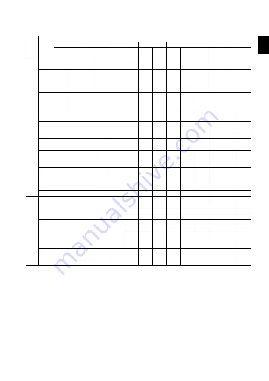
Notes
Cc (cooling capacity) – Pi (unit power input) – ELWT (evaporator leaving water temperature –
Δ
t 5°C).
Data are referred to 0,0176 m
2
°C/kW evaporator fouling factor.
C12
4
1,120
267
1,089
292
1,057
316
1,019
342
958
376
919
395
874
415
5
1,154
271
1,123
296
1,090
321
1,050
347
988
381
949
400
882
412
6
1,189
275
1,158
300
1,124
325
1,083
352
1,019
386
978
405
888
409
7
1,225
279
1,192
304
1,158
330
1,116
356
1,050
392
1,008
411
894
404
8
1,261
283
1,228
308
1,192
334
1,149
361
1,081
397
1,039
417
898
399
9
1,298
286
1,264
313
1,227
339
1,183
366
1,113
402
1,070
422
901
393
10
1,335
291
1,301
317
1,262
344
1,217
372
1,145
408
1,101
428
912
390
11
1,374
295
1,338
321
1,299
348
1,251
377
1,178
414
1,133
434
913
384
12
1,411
299
1,376
326
1,335
353
1,286
382
1,211
419
1,156
437
922
380
13
1,449
303
1,413
331
1,372
358
1,322
387
1,244
425
1,162
433
920
372
14
1,488
307
1,451
335
1,409
363
1,358
393
1,278
431
1,166
428
927
368
15
1,528
312
1,489
340
1,446
368
1,394
398
1,313
437
1,179
426
934
363
C13
4
1,237
295
1,203
321
1,167
348
1,124
377
1,057
414
1,014
435
964
457
5
1,275
299
1,241
326
1,204
353
1,160
382
1,090
420
1,046
441
973
455
6
1,315
303
1,279
331
1,241
358
1,196
387
1,124
426
1,079
447
976
452
7
1,354
307
1,318
335
1,279
363
1,232
393
1,158
432
1,112
453
976
448
8
1,395
312
1,358
340
1,318
368
1,269
398
1,194
437
1,146
459
980
445
9
1,436
316
1,398
345
1,357
374
1,307
404
1,229
444
1,181
465
983
441
10
1,478
321
1,439
350
1,397
379
1,345
410
1,265
450
1,216
472
990
438
11
1,521
325
1,481
355
1,437
384
1,384
415
1,302
456
1,251
478
990
433
12
1,564
330
1,523
360
1,478
390
1,423
421
1,338
462
1,273
480
993
429
13
1,607
335
1,565
365
1,519
395
1,463
427
1,376
469
1,278
478
1,001
427
14
1,651
340
1,608
370
1,561
401
1,503
433
1,414
475
1,282
475
1,003
422
15
1,695
345
1,652
375
1,603
407
1,544
440
1,452
482
1,285
471
1,009
419
C14
4
1,344
321
1,307
350
1,268
379
1,222
410
1,149
451
1,103
474
1,049
498
5
1,386
325
1,348
355
1,308
385
1,261
416
1,185
457
1,138
480
1,058
496
6
1,428
330
1,390
360
1,349
390
1,300
422
1,222
464
1,174
487
1,065
494
7
1,470
334
1,432
365
1,390
396
1,339
428
1,260
470
1,210
493
1,062
488
8
1,514
339
1,474
370
1,431
401
1,380
434
1,298
477
1,247
500
1,067
485
9
1,558
344
1,517
375
1,473
407
1,420
440
1,336
483
1,284
507
1,070
481
10
1,603
349
1,561
380
1,516
412
1,461
446
1,375
490
1,322
514
1,082
479
11
1,649
354
1,606
386
1,559
418
1,502
452
1,414
496
1,360
521
1,082
474
12
1,694
359
1,652
391
1,603
424
1,544
458
1,454
503
1,388
524
1,081
468
13
1,740
364
1,697
397
1,648
430
1,587
465
1,494
510
1,394
522
1,090
465
14
1,787
369
1,742
402
1,692
436
1,630
471
1,535
517
1,399
519
1,097
462
15
1,834
374
1,788
408
1,736
442
1,674
478
1,576
524
1,402
515
1,104
458
Size
ELWT
(°C)
Condenser Inlet Air Temperature (°C)
25
30
35
40
46
49
52
Cc
(kW)
Pi
(kW)
Cc
(kW)
Pi
(kW)
Cc
(kW)
Pi
(kW)
Cc
(kW)
Pi
(kW)
Cc
(kW)
Pi
(kW)
Cc
(kW)
Pi
(kW)
Cc
(kW)
Pi
(kW)
Summary of Contents for EWAD620-C17C-SS
Page 2: ......
Page 8: ...ESIE10 01 1 2 Part 1 System Outline 3 1 1 5...
Page 111: ...ESIE10 01 General Outline Part 1 System Outline 1 105 3 1 4 5 1 36 1 Power Compressor 1 2...
Page 112: ...General Outline ESIE10 01 1 106 Part 1 System Outline 3 1 1 4 5 1 36 2 Power Compressor 3...
Page 113: ...ESIE10 01 General Outline Part 1 System Outline 1 107 3 1 4 5 1 36 3 Kit Pumps...
Page 122: ...General Outline ESIE10 01 1 116 Part 1 System Outline 3 1 1 4 5 1 36 12 Digital Inputs Board...
Page 123: ...ESIE10 01 General Outline Part 1 System Outline 1 117 3 1 4 5 1 36 13 Digital Outputs Board...
Page 124: ...General Outline ESIE10 01 1 118 Part 1 System Outline 3 1 1 4 5 1 36 14 Digital Outputs Board...
Page 127: ...ESIE10 01 General Outline Part 1 System Outline 1 121 3 1 4 5 1 36 17 Extension Control Fans 4...
Page 131: ...ESIE10 01 General Outline Part 1 System Outline 1 125 3 1 4 5 1 36 21 EEXV Compressor 1...
Page 134: ...General Outline ESIE10 01 1 128 Part 1 System Outline 3 1 1 4 5 1 36 24 EEXV Compressor 2...
Page 137: ...ESIE10 01 General Outline Part 1 System Outline 1 131 3 1 4 5 1 36 27 EEXV Compressor 3...
Page 138: ...General Outline ESIE10 01 1 132 Part 1 System Outline 3 1 1 4 5 1 36 28 Pumps Control...
Page 139: ...ESIE10 01 General Outline Part 1 System Outline 1 133 3 1 4 5 1 36 29 Terminals M1 M2...
Page 140: ...General Outline ESIE10 01 1 134 Part 1 System Outline 3 1 1 4 5 1 36 30 Terminals M3...
Page 141: ...ESIE10 01 General Outline Part 1 System Outline 1 135 3 1 4 5 1 36 31 Terminals M5 MQ...
Page 148: ...General Outline ESIE10 01 1 142 Part 1 System Outline 3 1 1 4 5...
Page 150: ...ESIE10 01 2 2 Part 2 Functional Description 3 1 2 5...
Page 170: ...The Digital Controller ESIE10 01 2 22 Part 2 Functional Description 3 1 2 4 5...
Page 200: ...Functional Control ESIE10 01 2 52 Part 2 Functional Description 3 1 2 4 5...
Page 202: ...ESIE10 01 3 2 Part 3 Troubleshooting 3 1 3 5...
Page 254: ...Alarms and Events ESIE10 01 3 54 Part 3 Troubleshooting 3 1 3 4 5...
Page 266: ...Controller Inputs and Outputs ESIE10 01 3 66 Part 3 Troubleshooting 3 1 3 4 5...
Page 280: ...ESIE10 01 4 2 Part 4 Commissioning and Test Run 3 1 4 5...
Page 286: ...Pre Test Run Checks ESIE10 01 4 8 Part 4 Commissioning and Test Run 3 1 4 5...
Page 289: ...ESIE10 01 Running Data Part 4 Commissioning and Test Run 4 11 3 4 5 1...
Page 290: ...Running Data ESIE10 01 4 12 Part 4 Commissioning and Test Run 3 1 4 5...


