


General Outline
ESIE10-01
1–100
3
11
4
5
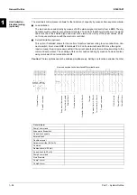
Note:
Water inlet and outlet are indicative. Please refer to the machine dimensional diagrams for exact
water connection of the partial recovery exchangers.
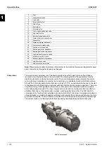
Compressor
The single-screw compressor is of the semi-hermetic type with an asynchronous three-phase,
two-pole motor directly splined on the main shaft. The suction gas from the evaporator cools the
electric motor before entering the suction ports. There are temperature sensors inside the electric
motor which are completely covered by the coil winding and constantly monitor motor temperature.
Should the coil winding temperature become very high (120°C), a special external device connected
to the sensors and to the electronic controller will deactivate the corresponding compressor. There are
only three moving rotating parts and there are no other parts in the compressor with an eccentric
and/or alternating movement. The basic components are therefore only the main rotor and the two
satellites that carry out the compression process, meshing perfectly together. The F3B and F4A
compressors are fitted with two satellites arranged horizontally to the screw. Compression sealing is
obtained thanks to a suitably-shaped special composite material that is interposed between the main
screw and the satellite. The main shaft on which the main rotor is splined is supported by ball bearings.
The system made up in this way is both statically and dynamically balanced before assembly.
6
Fans
7
Condensation bank
8
Load valve
9
2-way angle valve
10
Filter dryer
11
Sight glass
12
Solenoid valve
13
Thermostatic expansion valve
14
Non-return valve
15
Electronic expansion valve
16
Water outlet temp. transducer
17
Evaporator
18
Water inlet temp. transducer
19
Low-pressure safety valve
20
Suction valve (optional)
21
Suction gas temp. transducer
22
Suction gas press. transducer
23
High-pressure pressure switch
24
Oil/delivery press. transd.
25
Delivery gas temp. transducer
26
Liquid injection valve
27
Liquid injection mesh filter
F4AL compressor
Summary of Contents for EWAD620-C17C-SS
Page 2: ......
Page 8: ...ESIE10 01 1 2 Part 1 System Outline 3 1 1 5...
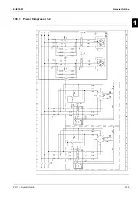
Page 111: ...ESIE10 01 General Outline Part 1 System Outline 1 105 3 1 4 5 1 36 1 Power Compressor 1 2...
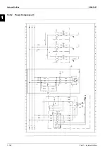
Page 112: ...General Outline ESIE10 01 1 106 Part 1 System Outline 3 1 1 4 5 1 36 2 Power Compressor 3...
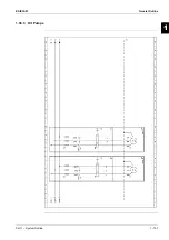
Page 113: ...ESIE10 01 General Outline Part 1 System Outline 1 107 3 1 4 5 1 36 3 Kit Pumps...
Page 122: ...General Outline ESIE10 01 1 116 Part 1 System Outline 3 1 1 4 5 1 36 12 Digital Inputs Board...
Page 123: ...ESIE10 01 General Outline Part 1 System Outline 1 117 3 1 4 5 1 36 13 Digital Outputs Board...
Page 124: ...General Outline ESIE10 01 1 118 Part 1 System Outline 3 1 1 4 5 1 36 14 Digital Outputs Board...
Page 127: ...ESIE10 01 General Outline Part 1 System Outline 1 121 3 1 4 5 1 36 17 Extension Control Fans 4...
Page 131: ...ESIE10 01 General Outline Part 1 System Outline 1 125 3 1 4 5 1 36 21 EEXV Compressor 1...
Page 134: ...General Outline ESIE10 01 1 128 Part 1 System Outline 3 1 1 4 5 1 36 24 EEXV Compressor 2...
Page 137: ...ESIE10 01 General Outline Part 1 System Outline 1 131 3 1 4 5 1 36 27 EEXV Compressor 3...
Page 138: ...General Outline ESIE10 01 1 132 Part 1 System Outline 3 1 1 4 5 1 36 28 Pumps Control...
Page 139: ...ESIE10 01 General Outline Part 1 System Outline 1 133 3 1 4 5 1 36 29 Terminals M1 M2...
Page 140: ...General Outline ESIE10 01 1 134 Part 1 System Outline 3 1 1 4 5 1 36 30 Terminals M3...
Page 141: ...ESIE10 01 General Outline Part 1 System Outline 1 135 3 1 4 5 1 36 31 Terminals M5 MQ...
Page 148: ...General Outline ESIE10 01 1 142 Part 1 System Outline 3 1 1 4 5...
Page 150: ...ESIE10 01 2 2 Part 2 Functional Description 3 1 2 5...
Page 170: ...The Digital Controller ESIE10 01 2 22 Part 2 Functional Description 3 1 2 4 5...
Page 200: ...Functional Control ESIE10 01 2 52 Part 2 Functional Description 3 1 2 4 5...
Page 202: ...ESIE10 01 3 2 Part 3 Troubleshooting 3 1 3 5...
Page 254: ...Alarms and Events ESIE10 01 3 54 Part 3 Troubleshooting 3 1 3 4 5...
Page 266: ...Controller Inputs and Outputs ESIE10 01 3 66 Part 3 Troubleshooting 3 1 3 4 5...
Page 280: ...ESIE10 01 4 2 Part 4 Commissioning and Test Run 3 1 4 5...
Page 286: ...Pre Test Run Checks ESIE10 01 4 8 Part 4 Commissioning and Test Run 3 1 4 5...
Page 289: ...ESIE10 01 Running Data Part 4 Commissioning and Test Run 4 11 3 4 5 1...
Page 290: ...Running Data ESIE10 01 4 12 Part 4 Commissioning and Test Run 3 1 4 5...


