


ESIE10-01
General Outline
1–19
3
1
4
5
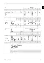
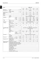
Model
EWAD~C-SL
C11
C12
C14
C15
C16
C17
Capacity
(1)
Cooling
kW 1064 1152 1419 1538 1622 1714
Capacity control
Type
Stepless
Minimum
capacity
%
12.5
12.5
7 7 7 7
Unit
power
input
(1)
Cooling
kW 378 402 500 551 580 618
EER (1)
2.82
2.86
2.84
2.79
2.8
2.77
ESEER
3.88 3.84 3.88 3.9 3.87 3.78
IPLV
4.17 4.19 4.19 4.22 4.18 4.13
Casing Colour
Ivory
White
Material
Galvanized and painted steel sheet
Dimensions
Unit
Height mm 2540 2540 2540 2540 2540 2540
Width mm 2285 2285 2285 2285 2285 2285
Length mm
7085 7985
10185
10185
11085
11085
Weight Unit
kg
7300
7570
10750
10770
11150
11210
Operating Weight
kg
7540
7810
11170
11170
11550
11700
Water heat
exchanger
Type
Single Pass Shell&Tube
Water
volume
l 243 243 421 408 408 474
Nominal water
flow rate
Cooling l/s 50.85 55.04 67.78 73.5 77.51 81.89
Nominal Water
pressure drop
Cooling
kPa
63 72 47 59 65 73
Insulation material
Closed cell
Air heat exchanger
Type
High efficiency fin and tube type with integral subcooler
Fan
Type
Direct propeller type
Drive DOL
Diameter mm
800
Nominal air flow
l/s
74822
85510
106888
106888
117577
117577
Model
Quantity
No.
14 16 20 20 22 22
Speed rpm 920 920 920 920 920 920
Motor
input
W 1.75 1.75 1.75 1.75 1.75 1.75
Compressor
Type
Semi-hermetic single screw compressor
Oil
charge
l 50 50 75 75 75 75
Quantity
No.
2 2 3 3 3 3
Sound level
Sound Power
Cooling
dB(A)
97.6
98.1
99.1
99.1
99.5
99.5
Sound Pressure
(2)
Cooling dB(A)
76.8 76.9 77.2 77.2 77.3 77.4
Refrigerant circuit
Refrigerant type
R-134a
Refrigerant
charge
kg
162 178 260 260 261 261
N.
of
circuits
No.
2 2 3 3 3 3
Piping connections
Evaporator water inlet/outlet
mm
168.3
168.3
219.1
219.1
219.1
219.1
Safety devices
High discharge pressure (pressure switch)
High discharge pressure (pressure transducer)
Low suction pressure (pressure transducer)
Compressor motor protection
High discharge temperature
Low oil pressure
Low pressure ratio
High oil filter pressure drop
Phase monitor
Emergency stop button
Water freeze protection controller
Summary of Contents for EWAD620-C17C-SS
Page 2: ......
Page 8: ...ESIE10 01 1 2 Part 1 System Outline 3 1 1 5...
Page 111: ...ESIE10 01 General Outline Part 1 System Outline 1 105 3 1 4 5 1 36 1 Power Compressor 1 2...
Page 112: ...General Outline ESIE10 01 1 106 Part 1 System Outline 3 1 1 4 5 1 36 2 Power Compressor 3...
Page 113: ...ESIE10 01 General Outline Part 1 System Outline 1 107 3 1 4 5 1 36 3 Kit Pumps...
Page 122: ...General Outline ESIE10 01 1 116 Part 1 System Outline 3 1 1 4 5 1 36 12 Digital Inputs Board...
Page 123: ...ESIE10 01 General Outline Part 1 System Outline 1 117 3 1 4 5 1 36 13 Digital Outputs Board...
Page 124: ...General Outline ESIE10 01 1 118 Part 1 System Outline 3 1 1 4 5 1 36 14 Digital Outputs Board...
Page 127: ...ESIE10 01 General Outline Part 1 System Outline 1 121 3 1 4 5 1 36 17 Extension Control Fans 4...
Page 131: ...ESIE10 01 General Outline Part 1 System Outline 1 125 3 1 4 5 1 36 21 EEXV Compressor 1...
Page 134: ...General Outline ESIE10 01 1 128 Part 1 System Outline 3 1 1 4 5 1 36 24 EEXV Compressor 2...
Page 137: ...ESIE10 01 General Outline Part 1 System Outline 1 131 3 1 4 5 1 36 27 EEXV Compressor 3...
Page 138: ...General Outline ESIE10 01 1 132 Part 1 System Outline 3 1 1 4 5 1 36 28 Pumps Control...
Page 139: ...ESIE10 01 General Outline Part 1 System Outline 1 133 3 1 4 5 1 36 29 Terminals M1 M2...
Page 140: ...General Outline ESIE10 01 1 134 Part 1 System Outline 3 1 1 4 5 1 36 30 Terminals M3...
Page 141: ...ESIE10 01 General Outline Part 1 System Outline 1 135 3 1 4 5 1 36 31 Terminals M5 MQ...
Page 148: ...General Outline ESIE10 01 1 142 Part 1 System Outline 3 1 1 4 5...
Page 150: ...ESIE10 01 2 2 Part 2 Functional Description 3 1 2 5...
Page 170: ...The Digital Controller ESIE10 01 2 22 Part 2 Functional Description 3 1 2 4 5...
Page 200: ...Functional Control ESIE10 01 2 52 Part 2 Functional Description 3 1 2 4 5...
Page 202: ...ESIE10 01 3 2 Part 3 Troubleshooting 3 1 3 5...
Page 254: ...Alarms and Events ESIE10 01 3 54 Part 3 Troubleshooting 3 1 3 4 5...
Page 266: ...Controller Inputs and Outputs ESIE10 01 3 66 Part 3 Troubleshooting 3 1 3 4 5...
Page 280: ...ESIE10 01 4 2 Part 4 Commissioning and Test Run 3 1 4 5...
Page 286: ...Pre Test Run Checks ESIE10 01 4 8 Part 4 Commissioning and Test Run 3 1 4 5...
Page 289: ...ESIE10 01 Running Data Part 4 Commissioning and Test Run 4 11 3 4 5 1...
Page 290: ...Running Data ESIE10 01 4 12 Part 4 Commissioning and Test Run 3 1 4 5...


