


Installation manual
7
ERHQ011~W1 + ERLQ011~W1
Outdoor unit for air to water heat pump
4PW54249-1
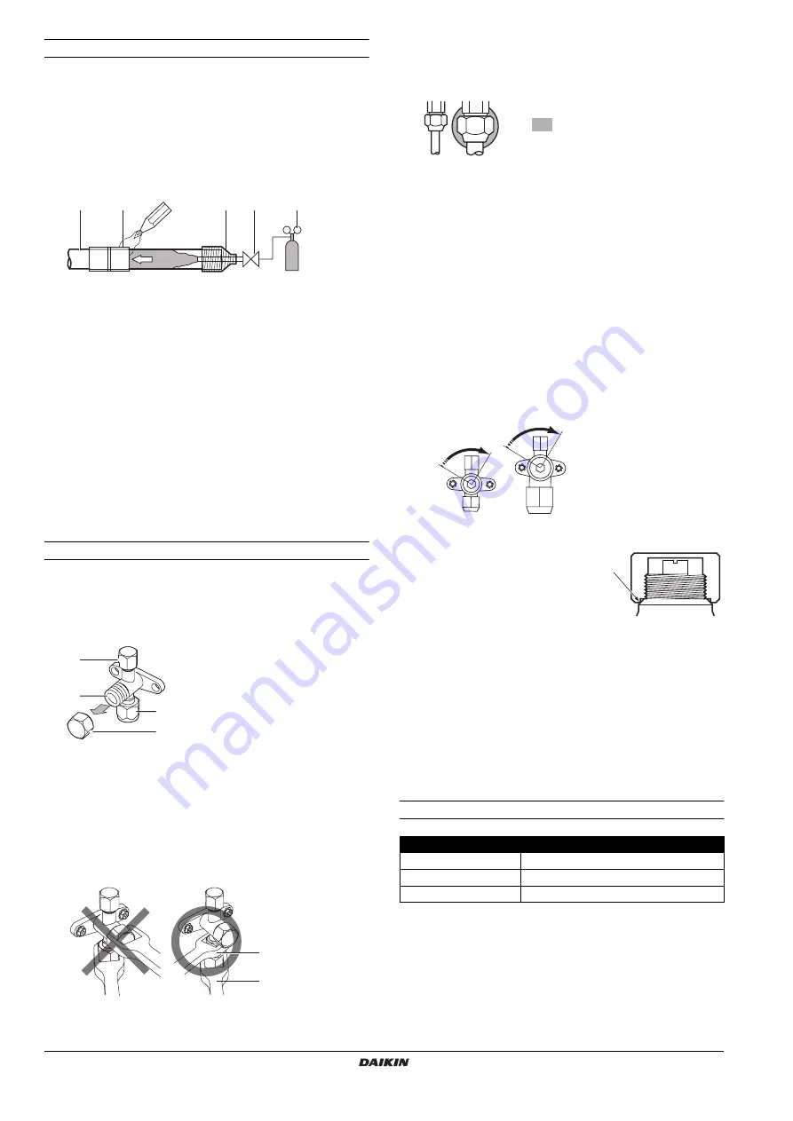
Brazing guidelines
■
Make sure to blow through with nitrogen when brazing.
Blowing through with nitrogen prevents the creation of large
quantities of oxidized film on the inside of the piping. An oxidized
film adversely affects valves and compressors in the
refrigerating system and prevents proper operation.
■
The nitrogen pressure should be set to 0.02 MPa (i.e., just
enough so it can be felt on the skin) with a pressure-reducing
valve.
■
Do not use anti-oxidants when brazing the pipe joints.
Residue can clog pipes and break equipment.
■
Do not use flux when brazing copper-to-copper refrigerant
piping. Use phosphor copper brazing filler alloy (BCuP) which
does not require flux.
■
Flux has an extremely harmful influence on refrigerant piping
systems. For instance, if chlorine based flux is used, it will cause
pipe corrosion or, in particular, if the flux contains fluorine, it will
deteriorate the refrigerant oil.
Stop valve operation
Cautions on handling the stop valve
■
Make sure to keep both stop valves open during operation.
■
The figure below shows the name of each part required in
handling the stop valve.
■
The stop valve is factory closed.
■
Do not apply excessive force to the valve stem. Doing so may
break the valve body.
■
Since the stop valve mounting plate may be deformed if only a
torque wrench is used to loosen or tighten the flare nut, always
make sure to secure the stop valve with a spanner, then loosen
or tighten the flare nut with a torque wrench.
Do not place the spanner on the stem cap, as this could cause a
refrigerant leak.
■
When it is expected that the operating pressure will be low (for
example, when cooling will be performed while the outside air
temperature is low), sufficiently seal the flare nut in the stop
valve on the gas line with silicon sealant to prevent freezing.
Opening/closing the stop valve
Opening the stop valve
1.
Remove the valve cover.
2.
Insert a hexagon wrench (liquid side: 4 mm/gas side: 6 mm) into
the valve stem and turn the valve stem counterclockwise.
3.
When the valve stem cannot be turned any further, stop turning.
The valve is now open.
Closing the stop valve
1.
Remove the valve cover.
2.
Insert a hexagon wrench (liquid side: 4 mm/gas side: 6 mm) into
the valve stem and turn the valve stem clockwise.
3.
When the valve stem cannot be turned any further, stop turning.
The valve is now closed.
Cautions on handling the stem cap
■
The stem cap is sealed where
indicated by the arrow. Take care not
to damage it.
■
After handling the stop valve, make
sure to tighten the stem cap securely.
For the tightening torque, refer to the
table below.
■
Check for refrigerant leaks after tightening the stem cap.
Cautions on handling the service port
■
Always use a charge hose equipped with a valve depressor pin,
since the service port is a Schrader type valve.
■
After handling the service port, make sure to tighten the service
port cap securely. For the tightening torque, refer to the table
below.
■
Check for refrigerant leaks after tightening the service port cap.
Tightening torques
1
Refrigerant piping
2
Part to be brazed
3
Taping
4
Manual valve
5
Pressure-reducing valve
6
Nitrogen
1
2
3
4
5
6
6
3
4
1
2
1
Service port and service port cap
2
Valve stem
3
Field piping connection
4
Stem cap
1
2
1
Spanner
2
Torque wrench
Silicon sealant
(Make sure there is no gap)
Closing direction
Liquid side
Gas side
Item
Tightening torque (N•m)
Stem cap, liquid side
13.5~16.5
Stem cap, gas side
22.5~27.5
Service port cap
11.5~13.9
Summary of Contents for ERLQ011BAV3
Page 20: ...4PW54249 1 Copyright Daikin...


