Installer reference guide
27
EHVH/X16
Daikin Altherma - Low Temperature Split
4P313777-1 – 2012.05
7 Installation
2
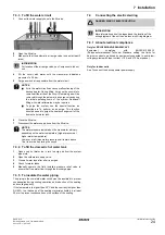
Fix the cable with cable ties to the cable tie mountings.
3
Configure the user interface for the respective power supply.
See Quick wizard: Standard.
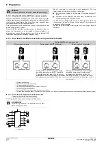
During connection of the backup heater, miswiring is possible. To
detect possible miswiring, it is highly recommended to measure the
resistance value of the heater elements. Depending on the different
backup heater types, following resistance values (see table below)
should be measured. ALWAYS measure the resistance on the
contactor clamps K1M, K2M, and K5M.
Example measure resistance between K1M/1 and K5M/13:
7.4.5 To connect the user interface
1
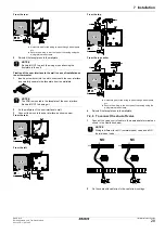
Connect the user interface cable to the indoor unit.
2
Fix the cable with cable ties to the cable tie mountings.
Fixation of the user interface to the indoor unit
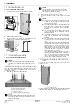
1
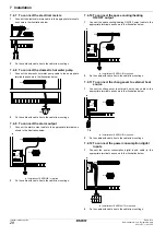
Insert a screwdriver into the slots underneath the user interface
and carefully separate the faceplate from the wallplate.
2
Fix the wallplate of the user interface to the frontplate of the unit.
3
Cut off a 2 wire conductor.
4
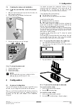
Connect the wires to the user interface as shown below.
3 kW
1~
230 V
6 kW
1~
230 V
6 kW
3~
230 V
6 kW
3N~
400 V
9 kW
3N~
400 V
K1M/1
K5M/13 52.9
Ω
52.9
Ω
52.9
Ω
∞
∞
K1M/3
∞
∞
∞
105.8
Ω
105.8
Ω
K1M/5
∞
∞
∞
105.8
Ω
105.8
Ω
K1M/3
K1M/5
26.5
Ω
26.5
Ω
26.5
Ω
105.8
Ω
105.8
Ω
K2M/1
K5M/13
∞
26.5
Ω
26.5
Ω
∞
∞
K2M/3
∞
∞
∞
52.9
Ω
52.9
Ω
K2M/5
∞
∞
∞
52.9
Ω
52.9
Ω
K2M/3
K2M/5
52.9
Ω
52.9
Ω
52.9
Ω
52.9
Ω
52.9
Ω
K1M/5
K2M/1
∞
∞
∞
∞
∞
K1M
K2M
K2M
K2M
1 3 5 13
2 4 6 14
K5M
1 3 5 13
2 4 6 14
1 3 5 13
2 4 6 14
Ω
Ω
a
User interface delivered with the unit
b
Optional user interface
NOTICE
The PCB is mounted in the faceplate of the user interface.
Be careful NOT to damage it.
NOTICE
Be careful NOT to distort the shape of the backside of the
user interface by overtightening the mounting screws.
X2M
X5M
A2P
A2P
2
1
a
b


