background image

7

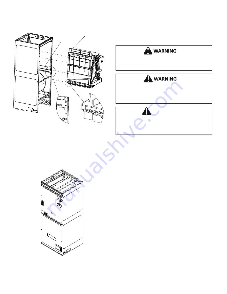
4.  Using the drain pan to hold the coil assembly, slide the coil 

assembly back into the cabinet on the downflow brackets as 

shown in Figure 8. 

Coil Slides on the
downflow bracket

IMPORTANT NOTE:

Ensure coil slides on the rails along the groove provided on the drain pan side walls.

Failure to do so will resul

n improper condensate drainage.

Remove Drain Pan Extension
before inserting coil for
downflow application

COIL INSTALLATION FOR DOWNFLOW

Figure 8

5.  Re-install the center support (if removed) using the two (2)  

screws removed in Step 4.

6.  Re-install the access panels removed in Step 1 as shown in 

Figure 9. 

ACCESS PANEL CONFIGURATION FOR DOWNFLOW OR 

HORIZONTAL RIGHT

Figure 9

7.  The bottom left drain connection is the primary drain for 

this application and condensate drain line must be attached 

to this drain connection. The top connection of the three 

drain connections on the drain pan must remain plugged for 

this application. The bottom left drain connection is for the 

secondary drain line (if used).

7  Refrigerant Lines

This product is factory-shipped with R410A and dry nitrogen 

mixture gas under pressure. Use appropriate service tools and 

follow these instructions to prevent injury.

A quenching cloth is strongly recommended to prevent 

scorching or marring of the equipment finish when brazing 

close to the painted surfaces. Use brazing alloy of 5% minimum 

silver content.

Applying too much heat to any tube can melt the tube. Torch

heat required to braze tubes of various sizes must be

proportional to the size of the tube. Service personnel must

use the appropriate heat level for the size of the tube being

brazed

.

CAUTION

NOTE:

 Refrigerant tubing must be routed to allow adequate 

access for servicing and maintenance of the unit.
Do not install the air handler in a location that violates the 

instructions provided with the condenser. If the unit is located in 

an unconditioned area with high ambient temperature and/or high 

humidity, the air handler may be subject to nuisance sweating 

of the casing. On these installations, a wrap of 2” fiberglass 

insulation with a vapor barrier is recommended. 

7.1 Tubing Size

For the correct tubing size, follow the specification for the 

condenser/heat pump.

7.2 Tubing Preparation

All cut ends are to be round, burr free, and clean.  Failure to 

follow this practice increases the chances for refrigerant leaks.  

The suction line is spun closed and requires tubing cutters to 

remove the closed end.

NOTE: To prevent possible damage to the tubing joints, do not 

handle coil assembly with manifold or flowrator tubes. Always 

use clean gloves when handling coil assemblies.

NOTE: The use of a heat shield is strongly recommended when 

brazing  to avoid burning the serial plate or the finish of the unit. 

Heat trap or wet rags must be used to protect heat sensitive 

components such as service valves and TXV valves sensing 

bulb.

7.3 Tubing Connections for TXV Models

  TXV models come with factory installed TXV with the bulb 

pre-installed on the vapor tube.

1.  Remove refrigerant tubing panel or coil (lower) access panel.  

2.  Remove access valve fitting cap and depress the valve stem 

in access fitting to release pressure. No pressure indicates 

possible leak.

Summary of Contents for DV PTC 14 Series

Page 1: ...ations 3 4 Replacement Parts 3 5 Pre Installation Considerations 3 5 1 Preparation 3 5 2 System Matches 3 5 3 Interconnecting Tubing 4 5 4 Clearances 4 5 5 Horizontal Applications 4 6 Installation Loc...

Page 2: ...E Disconnect ALL power before servicing or installing this unit Multiple power sources may be present Failure to do so may cause property damage personal injury or death This product is factory shippe...

Page 3: ...g at the cabinet corners 3 Codes Regulations This product is designed and manufactured to comply with applicable national codes Installation in accordance with such codes and or prevailing local codes...

Page 4: ...hat may become wet such as crawl spaces elevate the unit with a sturdy non porous material In installations that may lead to physical damage i e a garage it is advised to install a protective barrier...

Page 5: ...CB14 DV33PTCC14 DV61PTCD14 DV39PTCC14 DV49PTCC14 DFK C DFK D Downflow Kit Downflow Kit Downflow Kit MODEL LIST FOR DOWNFLOW KITS DFK B Downflow Kit Table 2 Refer to Figure 6 and 7 for the location of...

Page 6: ...Center Support Filter Bracket Filter Access Panel INTERNAL PART TERMINOLOGY Figure 6 Blower Access Panel Coil Access Panel Tubing Panel UV Knockout EXTERNAL PART TERMINOLOGY Figure 7 NOTE If removing...

Page 7: ...t be proportional to the size of the tube Service personnel must use the appropriate heat level for the size of the tube being brazed CAUTION NOTE Refrigerant tubing must be routed to allow adequate a...

Page 8: ...superheat is low adjust TXV valve to 7 to 9 superheat and remove charge to lower the subcooling to 7 to 9 F NOTE Do NOT adjust the charge based on suction pressure unless there is a gross undercharge...

Page 9: ...per field constructed P style trap than is shown in Figure 12 to allow proper drainage and prevent condensate overflow Air Handler 2 75 MIN POSITIVE LIQUID SEAL REQUIRED AT TRAP Drain Connection 2 MIN...

Page 10: ...nit s Serial and Rating plate or the HKS specification sheets to determine the heat kits compatible with a given air handler No other accessory heat kit besides the HKS series may be installed in thes...

Page 11: ...your unit FIRE HAZARD To avoid the risk of property damage personal injury or fire use only copper conductors CAUTION HIGH VOLTAGE Failure to do so may cause property damage personal injury or death D...

Page 12: ...of the cabinet or either side See the Thermostat Wiring section of this manual for typical low voltage wiring connections 13 Achieving 1 4 and 2 0 Airflow Low Leakage Rate Ensure all the gaskets rema...

Page 13: ...ween Y1 and O for Proper Dehumidification Operation and Proper Ramping Profile Operation W2 Typical Single Stage Cooling with Single Stage Heating Figure 14 Air Handler Integrated Control Module Typic...

Page 14: ...CH Figure 19 Legacy mode use In a legacy system Non communicating this feature is not operational Any auxiliary alarm switch must be used to interrupt the Y1 signal either to the indoor or outdoor uni...

Page 15: ...flow for the cooling system Most cooling systems are designed to work with airflows between 350 and 450 CFM per ton Most manufacturers recommend an airflow of about 400 CFM per ton Example 2 5 tons X...

Page 16: ...R NR NR NR NR NR 1750 NR 25 OFF OFF OFF NR NR NR NR NR NR NR NR NR NR NR 1750 NR Note Airflow data shown applies to the electric heat only in either legacy mode or communicating mode operation Within...

Page 17: ...s maximum airflow capability is 2000 CFM and 25 continuous fan speed is selected the continuous fan speed will be 0 25 x 2000 CFM 500 CFM 6 The multi speed circulator blower also offers several custo...

Page 18: ...code from being displayed NOTE For installations not indicated in the preceding Temperature Rise Tables the following formula is to be used TR kW x 3412 x Voltage Correction 1 08 x CFM Where TR Tempe...

Page 19: ...ypically do not return information to the thermostat On the other hand the indoor unit outdoor unit and thermostat comprising a Communicating system communicate digitally with one another It is now a...

Page 20: ...to terminal 1 on indoor unit and thermostat and data line terminal 2 from AC HP must connect to terminal 2 on indoor unit and thermostat Verify wires are not reversed ATTENTION INSTALLER IMPORTANT NO...

Page 21: ...led when necessary and pitched to allow for drainage Drain pan and drain tubing has been leak checked Return and supply ducts are sealed Unit is elevated when installed in a garage or where flammable...

Page 22: ...a 1 data 2 wires Check wire connections at terminal block Verify air handler installation type noncommunicating traditional or communicating Check data 1 data 2 voltages Turn power OFF prior to repair...

Page 23: ...tory NOTE Consecutively repeated faults are shown a maximum of 3 times Submenu Item Model Number MOD NUM Displays the modular blower model number Serial Number SER NUM Displays the modular blower seri...

Page 24: ...ENT TRIP OR LOST ROTOR b5 BLOWER MOTOR ROTOR LOCKED b6 OVER UNDER VOLTAGE TRIP OR OVER TEMPERATURE TRIP b7 INCOMPLETE PARAMETER SENT TO MOTOR b9 LOW INDOOR AIRFLOW C1 LOW STAGE COOL LEGACY MODE ONLY C...

Page 25: ...ROL LOW VOLTAGE 24V FIELD SPLICE INTERNAL TO FIELD GRND OVERCURRENT BK BLACK OR ORANGE BL BLUE PK PINK GY GRAY RD RED WH WHITE PU PURPLE YL YELLOW BR BROWN COLOR CODES GN GREEN NOTES 1 PLACE RED WIRES...

Page 26: ...ERVICING MULTIPLE POWER SOURCES MAY BE PRESENT FAILURE TO DO SO MAY CAUSE PROPERTY DAMAGE PERSONAL INJURY OR DEATH WARNING Wiring is subject to change Always refer to the wiring diagram on the unit fo...

Page 27: ...uminum tube and fin evaporator coils Even a one time application of these corrosive chemicals can cause premature aluminum evaporator coil failure Any cleaners that contain corrosive chemicals includi...

Page 28: ...F WB F Heating Supply AirTemperature DB F Temperature Rise DB F DeltaT Difference between Supply and Return Temperatures DB F AirHandler Coil InverterMatched INVERTERAH COILONLY Check EEV and EEV wiri...

Page 29: ...29 THIS PAGE INTENTIONALLY LEFT BLANK...

Page 30: ...30 THIS PAGE INTENTIONALLY LEFT BLANK...

Page 31: ...31 THIS PAGE INTENTIONALLY LEFT BLANK...

Page 32: ...register by following this link https daikincomfort com owner support product registration You can also scan the QR code on the right to be directed to the Product Registration page CUSTOMER FEEDBACK...

Reviews: