25
HIGH VOLTAGE!
DISCONNECT ALL POWER BEFORE SERVICING.
MULTIPLE POWER SOURCES MAY BE PRESENT. FAILURE TO DO SO
MAY CAUSE PROPERTY DAMAGE, PERSONAL INJURY OR DEATH.
WARNING
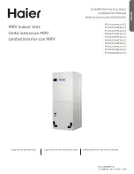
23 Wiring Diagrams
Wiring is subject to change. Always refer to the wiring diagram on the unit for the most up-to-date wiring.
CO
NT
F
A
N
4 CIRCUIT HEATER
CONNECTOR
COM
CIRCULATOR BLOWER
1
1
SEE NOTE 6
CIRCULATOR
CIRCULATOR
RD
WH
TO
MICRO
R
CAS (1)
AIR
230 VAC
7 SEGMENT
DIAGNOSTIC
DISPLAY
PL1
SEE
NOTE 7
O
DEHUM
4
CI
R
CUI
T
M
O
T
O
R
C
O
NNE
CT
O
R
24 VAC
RD
4
BLWR
LEARN
5
DIP SWITCHES
AIR
40 VA
2
3
1
2
8
40 VA TRANSFORMER, SEE NOTE 1
L1
9
INDOOR
7
24 VAC
4
BK
1
5
BL
PL2
FUSE 3 A
208/230 VAC
GRND
ECM MOTOR
HARNESS
GRND
6
L2
6
L1
COM
BR
G
G
INTEGRATED CONTROL MODULE
O
4
3
W2
BK
3
1
24V
T
HE
RM
O
S
T
A
T
CO
NNE
CT
IO
NS
COM
W2
L2
DISCONNECT
SEE NOTE 5
2
BL
Y2
BK
TR
C
1
3
GRND (4)
2
2
INDOOR
9
RD
TH
+VDC (1)
Y1
208 VAC
TH
BK
Y2
RX (2)
RD
GRND
4
24 V 3 A
W1
GRND
4
GN
Y1
R
FAULT
RECALL
W1
8
5
W1 (1)
C
RD
DEHUM
TX (3)
BL
TWO-STAGE INTEGRATED CONTROL MODULE
3
GRND
HEAT 2 COIL/ R2
RD
TRANSFORMER
24
V
T
HE
RM
O
S
T
A
T
CO
NNE
CT
IO
NS
HEAT 1 COIL/R1
GN
7
TR
2
BLWR
EQUIPMENT GRND
TERMINAL
PLUG CONNECTION
LOW VOLTAGE FIELD
HI VOLTAGE FIELD
JUNCTION
HI VOLTAGE (230V)
PROT. DEVICE
INTEGRATED CONTROL
LOW VOLTAGE (24V)
FIELD SPLICE
INTERNAL TO
FIELD GRND
OVERCURRENT
BK ---- BLACK
OR ---- ORANGE
BL ---- BLUE
PK ---- PINK
GY ---- GRAY
RD ---- RED
WH ----WHITE
PU ---- PURPLE
YL ---- YELLOW
BR ---- BROWN
COLOR CODES:
GN ---- GREEN
NOTES:
1. PLACE RED WIRES ON TRANSFORMER TERMINAL 2 FOR 208 VAC OPERATION.
2. MANUFACTURER'S SPECIFIED REPLACEMENT PARTS MUST BE USED WHEN SERVICING.
3. IF ANY OF THE ORIGINAL WIRES AS SUPPLIED WITH THIS UNIT MUST BE REPLACED,
IT MUST BE REPLACED WITH WIRING MATERIAL HAVING A TEMPERATURE RATING OF AT
LEAST 105°C. USE COPPER CONDUCTORS ONLY.
4. UNIT MUST BE PERMANENTLY GROUNDED AND CONFORM TO N.E.C AND LOCAL CODES.
5. TO RECALL THE LAST 6 FAULTS, MOST RECENT TO LEAST RECENT, DEPRESS
SWITCH FOR MORE THAN 2 SECONDS WHILE IN STANDBY (NO THERMOSTAT INPUTS)
6. RED STATUS LED PROVIDES NETWORK STATUS. GREEN RX LED INDICATES NETWORK TRAFFIC.
USE LEARN BUTTON TO RESET NETWORK.
7. DISCARD CONNECTOR PL1 WHEN INSTALLING OPTIONAL HEAT KIT.
8. THE CONDENSATE ALARM SWITCH (CAS) TERMINALS CAN ONLY BE UTILIZED WITH COMMUNICATING
MODE SETUPS AND MUST BE ENABLED WITH A COMMUNICATING THERMOSTAT. THIS FEATURE IS NOT
OPERATIONAL WITH LEGACY SYSTEMS.
9. USE N.E.C CLASS 2 WIRE.
0140A00244-C
1
2
3
CONDENSATE SWITCH
CAS (2)
W2 (2)
FUSE
CAS
SEE NOTE 8
CFM LED
STATUS
LED
SEE NOTE 6
SEE NOTE 6
RX LED
H
TR
K
IT(
K
W
)
C
O
O
L
A
F P
R
O
F
IL
E
DE
HUM
E
NA
B
LE
T
R
IM
EN
ABL
E
TR
IM
%
AF
SEL
EC
T
RESISTOR
S
1
S
2
S
3
S
4
S
5
S
6
S
7
S
8
S
9
S1
0
S1
1
S12
S1
3
4 3 2
1
C
W2
W1
BL
GY
BK
RD
SEE
N
O
T
E
9
SEE
N
O
TE
9