background image

18

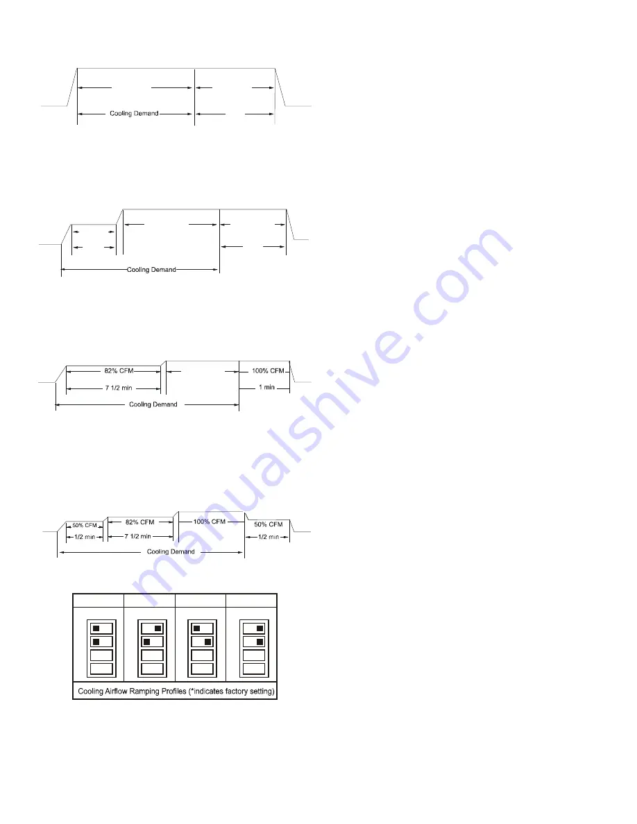
•  Profile A provides only an OFF delay of one (1) minute at 

100% of the cooling demand airflow.

OFF

100% CFM

100% CFM

1 min

OFF

Figure 26

•  Profile B ramps up to full cooling demand airflow by first 

stepping up to 50% of the full demand for 30 seconds.  The 

motor then ramps to 100% of the required airflow.  A one (1) 

minute OFF delay at 100% of the cooling airflow.

50% CFM

1/2 min

100% CFM

100% CFM

1 min

OFF

OFF

Figure 27

•  Profile C ramps up to 82% of the full cooling demand airflow 

and operates there for approximately 7 1/2 minutes.  The 

motor then steps up to the full demand airflow. Profile C also 

has a one (1) minute 100% OFF delay.

100% CFM

OFF

OFF

Figure 28

•  Profile D ramps up to 50% of the demand for 1/2 minute, 

then ramps to 82% of the full cooling demand airflow and 

operates there for approximately 7 1/2 minutes.  The motor 

then steps up to the full demand airflow.  Profile D has a 1/2 

minute at 50% airflow OFF delay.

OFF

OFF

Figure 29

S5
S6

S5
S6

S5
S6

S5
S6

OFF

OFF

OFF

OFF

ON

ON

ON

ON

Tap A*

Tap B

Tap C

Tap D

Dip Switches - Cooling Airflow Ramping Profiles

Figure 30

7.  If an electric heater kit has been installed, determine the 

heater kilowatt (kW) rating.  Using the Electric Heat Airflow 

table on page 16, set dip switches 9, 10, and 11 for the 

installed heater. The adjust setting (already established 

by the cooling speed selection) also applies to the electric 

heater kit airflow meaning electric heater airflow is adjusted 

by the same amount. This does not apply to systems setup 

with a communicating thermostat. Verify selected CFM by 

counting the green CFM LED blinks.

  If an electric heater kit has not been installed, set dip 

switches 9, 10, and 11 to any valid heater kit setting (see 

airflow table for valid settings).  This will prevent an Ec Error 

code from being displayed.

NOTE:

 For installations not indicated in the preceding 

Temperature Rise Tables, the following formula is to be used:

        TR = (kW x 3412) x (Voltage Correction) / (1.08 x CFM)

  Where: 

TR 

=  Temperature Rise

  kW = Heater Kit Actual kW
  3412 

= Btu per kW

  Voltage Correction  =.96 (230 Supply Volts)


=.92 (220 Supply Volts)


=.87 (208 Supply Volts)

        1.08   = Constant
        CFM  = Measured Airflow

NOTE: 

The Temperature Rise Tables can also be used to 

determine the air handler airflow delivery.  When using these 

tables for this purpose set the room thermostat to maximum heat 

and allow the system to reach steady state conditions.  Insert two 

thermometers, one in the return air and one in the supply air.  The 

temperature rise is the supply air temperature minus the room air 

temperature.

Use HKR specification sheets to determine the HKR available for 

a given air handler.

Heat Kit Selection

For heat kit selection, see the Specification Sheet for each 

specific Air Handler.

17  Troubleshooting

17.1 Electrostatic Discharge (ESD) Precautions 
NOTE: 

 Discharge body’s static electricity before touching 

unit.  An electrostatic discharge can adversely affect electrical 

components.
Use the following precautions during air handler installation 

and servicing to protect the integrated control module from 

damage.  By putting the air handler, the control, and the person 

at the same electrostatic potential, these steps will help avoid 

exposing the integrated control module to electrostatic discharge.  

This procedure is applicable to both installed and uninstalled 

(ungrounded) blowers.

1.  Disconnect all power to the blower.  Do not touch the 

integrated control module or any wire connected to the 

control prior to discharging your body’s electrostatic charge 

to ground.

2.  Firmly touch a clean, unpainted, metal surface of the air 

handler blower near the control.  Any tools held in a person’s 

hand during grounding will be discharged.

3.  Service integrated control module or connecting wiring 

Summary of Contents for DV PTC 14 Series

Page 1: ...ations 3 4 Replacement Parts 3 5 Pre Installation Considerations 3 5 1 Preparation 3 5 2 System Matches 3 5 3 Interconnecting Tubing 4 5 4 Clearances 4 5 5 Horizontal Applications 4 6 Installation Loc...

Page 2: ...E Disconnect ALL power before servicing or installing this unit Multiple power sources may be present Failure to do so may cause property damage personal injury or death This product is factory shippe...

Page 3: ...g at the cabinet corners 3 Codes Regulations This product is designed and manufactured to comply with applicable national codes Installation in accordance with such codes and or prevailing local codes...

Page 4: ...hat may become wet such as crawl spaces elevate the unit with a sturdy non porous material In installations that may lead to physical damage i e a garage it is advised to install a protective barrier...

Page 5: ...CB14 DV33PTCC14 DV61PTCD14 DV39PTCC14 DV49PTCC14 DFK C DFK D Downflow Kit Downflow Kit Downflow Kit MODEL LIST FOR DOWNFLOW KITS DFK B Downflow Kit Table 2 Refer to Figure 6 and 7 for the location of...

Page 6: ...Center Support Filter Bracket Filter Access Panel INTERNAL PART TERMINOLOGY Figure 6 Blower Access Panel Coil Access Panel Tubing Panel UV Knockout EXTERNAL PART TERMINOLOGY Figure 7 NOTE If removing...

Page 7: ...t be proportional to the size of the tube Service personnel must use the appropriate heat level for the size of the tube being brazed CAUTION NOTE Refrigerant tubing must be routed to allow adequate a...

Page 8: ...superheat is low adjust TXV valve to 7 to 9 superheat and remove charge to lower the subcooling to 7 to 9 F NOTE Do NOT adjust the charge based on suction pressure unless there is a gross undercharge...

Page 9: ...per field constructed P style trap than is shown in Figure 12 to allow proper drainage and prevent condensate overflow Air Handler 2 75 MIN POSITIVE LIQUID SEAL REQUIRED AT TRAP Drain Connection 2 MIN...

Page 10: ...nit s Serial and Rating plate or the HKS specification sheets to determine the heat kits compatible with a given air handler No other accessory heat kit besides the HKS series may be installed in thes...

Page 11: ...your unit FIRE HAZARD To avoid the risk of property damage personal injury or fire use only copper conductors CAUTION HIGH VOLTAGE Failure to do so may cause property damage personal injury or death D...

Page 12: ...of the cabinet or either side See the Thermostat Wiring section of this manual for typical low voltage wiring connections 13 Achieving 1 4 and 2 0 Airflow Low Leakage Rate Ensure all the gaskets rema...

Page 13: ...ween Y1 and O for Proper Dehumidification Operation and Proper Ramping Profile Operation W2 Typical Single Stage Cooling with Single Stage Heating Figure 14 Air Handler Integrated Control Module Typic...

Page 14: ...CH Figure 19 Legacy mode use In a legacy system Non communicating this feature is not operational Any auxiliary alarm switch must be used to interrupt the Y1 signal either to the indoor or outdoor uni...

Page 15: ...flow for the cooling system Most cooling systems are designed to work with airflows between 350 and 450 CFM per ton Most manufacturers recommend an airflow of about 400 CFM per ton Example 2 5 tons X...

Page 16: ...R NR NR NR NR NR 1750 NR 25 OFF OFF OFF NR NR NR NR NR NR NR NR NR NR NR 1750 NR Note Airflow data shown applies to the electric heat only in either legacy mode or communicating mode operation Within...

Page 17: ...s maximum airflow capability is 2000 CFM and 25 continuous fan speed is selected the continuous fan speed will be 0 25 x 2000 CFM 500 CFM 6 The multi speed circulator blower also offers several custo...

Page 18: ...code from being displayed NOTE For installations not indicated in the preceding Temperature Rise Tables the following formula is to be used TR kW x 3412 x Voltage Correction 1 08 x CFM Where TR Tempe...

Page 19: ...ypically do not return information to the thermostat On the other hand the indoor unit outdoor unit and thermostat comprising a Communicating system communicate digitally with one another It is now a...

Page 20: ...to terminal 1 on indoor unit and thermostat and data line terminal 2 from AC HP must connect to terminal 2 on indoor unit and thermostat Verify wires are not reversed ATTENTION INSTALLER IMPORTANT NO...

Page 21: ...led when necessary and pitched to allow for drainage Drain pan and drain tubing has been leak checked Return and supply ducts are sealed Unit is elevated when installed in a garage or where flammable...

Page 22: ...a 1 data 2 wires Check wire connections at terminal block Verify air handler installation type noncommunicating traditional or communicating Check data 1 data 2 voltages Turn power OFF prior to repair...

Page 23: ...tory NOTE Consecutively repeated faults are shown a maximum of 3 times Submenu Item Model Number MOD NUM Displays the modular blower model number Serial Number SER NUM Displays the modular blower seri...

Page 24: ...ENT TRIP OR LOST ROTOR b5 BLOWER MOTOR ROTOR LOCKED b6 OVER UNDER VOLTAGE TRIP OR OVER TEMPERATURE TRIP b7 INCOMPLETE PARAMETER SENT TO MOTOR b9 LOW INDOOR AIRFLOW C1 LOW STAGE COOL LEGACY MODE ONLY C...

Page 25: ...ROL LOW VOLTAGE 24V FIELD SPLICE INTERNAL TO FIELD GRND OVERCURRENT BK BLACK OR ORANGE BL BLUE PK PINK GY GRAY RD RED WH WHITE PU PURPLE YL YELLOW BR BROWN COLOR CODES GN GREEN NOTES 1 PLACE RED WIRES...

Page 26: ...ERVICING MULTIPLE POWER SOURCES MAY BE PRESENT FAILURE TO DO SO MAY CAUSE PROPERTY DAMAGE PERSONAL INJURY OR DEATH WARNING Wiring is subject to change Always refer to the wiring diagram on the unit fo...

Page 27: ...uminum tube and fin evaporator coils Even a one time application of these corrosive chemicals can cause premature aluminum evaporator coil failure Any cleaners that contain corrosive chemicals includi...

Page 28: ...F WB F Heating Supply AirTemperature DB F Temperature Rise DB F DeltaT Difference between Supply and Return Temperatures DB F AirHandler Coil InverterMatched INVERTERAH COILONLY Check EEV and EEV wiri...

Page 29: ...29 THIS PAGE INTENTIONALLY LEFT BLANK...

Page 30: ...30 THIS PAGE INTENTIONALLY LEFT BLANK...

Page 31: ...31 THIS PAGE INTENTIONALLY LEFT BLANK...

Page 32: ...register by following this link https daikincomfort com owner support product registration You can also scan the QR code on the right to be directed to the Product Registration page CUSTOMER FEEDBACK...

Reviews: