


25
SERVICING
1/4
cu/ft
1/2
cu/ft
1
cu/ft
2
cu/ft
5
cu/ft
10
90
180
360
720
1800
11
82
164
327
655
1636
12
75
150
300
600
1500
13
69
138
277
555
1385
14
64
129
257
514
1286
15
60
120
240
480
1200
16
56
113
225
450
1125
17
53
106
212
424
1059
18
50
100
200
400
1000
19
47
95
189
379
947
20
45
90
180
360
900
21
43
86
171
343
857
22
41
82
164
327
818
23
39
78
157
313
783
24
37
75
150
300
750
25
36
72
144
288
720
26
34
69
138
277
692
27
33
67
133
265
667
28
32
64
129
257
643
29
31
62
124
248
621
30
30
60
120
240
600
31
--
--
116
232
581
32
28
56
113
225
563
33
--
--
109
218
545
34
26
53
106
212
529
35
--
--
103
206
514
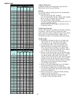
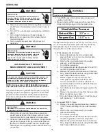
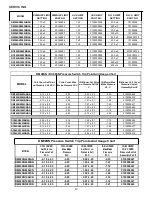
Size of Test Dial
GAS RATE -- CUBIC FEET PER HOUR
Seconds for
One
Revolution
1/4
cu/ft
1/2
cu/ft
1
cu/ft
2
cu/ft
5
cu/ft
36
25
50
100
200
500
37
--
--
97
195
486
38
23
47
95
189
474
39
--
--
92
185
462
40
22
45
90
180
450
41
--
--
--
176
439
42
21
43
86
172
429
43
--
--
--
167
419
44
--
41
82
164
409
45
20
40
80
160
400
46
--
--
78
157
391
47
19
38
76
153
383
48
--
--
75
150
375
49
--
--
--
147
367
50
18
36
72
144
360
51
--
--
--
141
355
52
--
--
69
138
346
53
17
34
--
136
340
54
--
--
67
133
333
55
--
--
--
131
327
56
16
32
64
129
321
57
--
--
--
126
316
58
--
31
62
124
310
59
--
--
--
122
305
60
15
30
60
120
300
GAS RATE -- CUBIC FEET PER HOUR
Seconds for
One
Revolution
Size of Test Dial
Combustion Quality
Combustion quality can be affected by several factors.
Major factors are venting and draining.
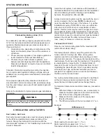
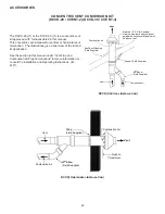
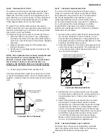
Venting
The venting system should be planned and installed with
the following in mind:
•
Should not be longer than necessary
•
Use 45° elbows rather than 90° elbows when possible
•
Must not sag or otherwise trap condensate
•
Use longest radius fittings possible
•
If using 3" venting, make the transition from 2" to 3" as
close as practically possible
•
Make sure there is no flue gas recirculation into the
combustion air pipe
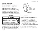
Condensate Drainage
Furnace combustion can be affected if a furnace is holding
condensate. Check for proper connections of drain
hoses; make sure furnace condensate trap is clean. Make
sure furnace is not improperly sloped. Make sure air
conditioning coil drain is not interfering with furnace drain.
Other Causes
1. Manifold Gas Pressure must be set, the gas being
used, Natural or L.P., high and low firing rates. If
converted to L.P. gas, check size of all orifices.
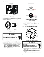
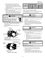
2. Remove Draft Inducer, Check the integrity of the
gasket between the inducer and the collector box
cover, any air leak here will have a negative effect
on combustion. Check the orifice hole in the collector
box, it must be free or burrs on both sides.
3. Make sure burners are clean, not out of position and
line up correctly with heat exchanger tubes, including
the heat exchanger orifice plate - this is the plate
which mounts to the front panel of the heat exchanger
between the burners and the heat exchanger tubes,
make sure it is not loose, missing a screw or hanging
down between the burners and heat exchanger
causing flame impingement.
4. Make sure the field installed gas line is not binding
and causing distortion of burner assembly.
5. If the furnace is installed as a one pipe system; make
sure the surrounding area and structure are adequate
to provide combustion air.
6. Make sure there are no cabinet air leakes allowing
supply air to affect combustion.
7. If heat exchanger integrity is uncertain, follow
procedures in Service Bulletin SF-041.


