


15
SYSTEM OPERATION
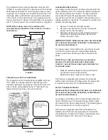
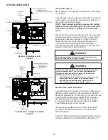
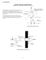
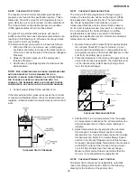
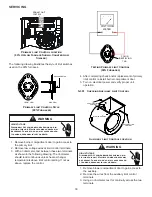
200 PSIG
Maximum
5 to 15 PSIG
(20 PSIG Max.)
Continuous
11" W.C.
Second Stage
Regulator
First Stage
Regulator
Propane Gas Installation (Typ.)
Figure 10
For satisfactory operation, propane gas pressure must be
10” WC at the furnace manifold with all gas appli ances in
operation. Maintaining proper gas pressure depends on
three main factors:
1. Vaporization rate, depending on temperature of the
liquid, and “wetted surface” area of the con tainer or
containers.
2. Proper pressure regulation. (Two-stage regulation is
recommended for both cost and efficiency).
3. Pressure drop in lines between regulators, and
between second stage regulator and the appliance.
Pipe size will depend on length of pipe run and total
load of all appliances.
Complete information regarding tank sizing for vaporiza-
tion, recommended regulator settings, and pipe sizing is
available from most regulator manufacturers and propane
gas suppliers.
Since propane gas will quickly dissolve white lead and
most standard com mercial compounds, special pipe dope
must be used. Always use a pipe thread sealant approved
for all gases.
Refer to the illustration for typical propane gas installations
and piping.
WARNING
Never allow the products of combustion, including carbon
monoxide to enter the return duct work or circulation air
supply.
CIRCULATING AIR & FILTERS
Duct work - Air Flow
Duct systems and register sizes must be properly designed
for the CFM and external static pressure rat ing of the
furnace. Design the ductwork in accor dance with the
recommended methods of “Air Conditioning Contractors of
America” Manual D.
Install the duct system in accordance with Standards of
the National Board of Fire Underwriters for the Installation
of Air Conditioning, Warm Air Heating and Ventilating
Systems. Pamphlets No. 90A and 90B.
A closed return duct system must be used, with the return
duct connected to the furnace.
NOTE:
Ductwork must
never be attached to the back of the furnace. For upflow
installations requiring 1800 CFM or more, use either two
side returns or bottom return or a combination of side /
bottom. Flexible joints may be used for supply and return
con nections to reduce noise transmission. To prevent the
blower from inter fering with combustion air or draft when a
central return is used, a connecting duct must be installed
between the unit and the utility room wall. Never use a
room, closet, or alcove as a return air chamber.
Checking Duct Static
Refer to your furnace rating plate for the maximum ESP
(external duct static) rating.
Total external static refers to everything external to the
furnace cabinet. Cooling coils, filters, ducts, grilles,
registers must all be considered when reading your total
external static pressure. The supply duct pressure must be
read between the furnace and the cooling coil. This reading
is usually taken by removing the “A” shaped block off
plate from the end on the coil; drilling a test hole in it and
reinstalling the block off plate. Take a duct static reading
at the test hole. Tape up the test hole after your test is
complete. The negative pressure must be read between
the filter and the furnace blower.
Too much external static pressure will result in insufficient
air that can cause excessive temperature rise. This can
cause limit switch tripping and heat exchanger failure.
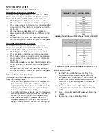
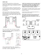
To determine total external duct static pressure, proceed as
follows:
1. With clean filters in the furnace, use a manometer to
measure the static pressure of the return duct at the
inlet of the furnace. (Negative Pressure)
2. Measure the static pressure of the supply duct.
(Positive Pressure)
3. The difference between the two numbers is .4” w.c.
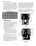
Example:
-1
0
1
2
3
Difference is 4
Static reading from return duct = -.1” w.c.
Static reading from supply duct = .3” w.c.
Total external static pressure on this system = .4” w.c.


