


12
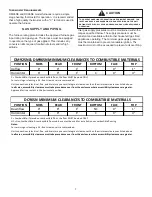
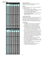
Inlet gas supply pressures must be maintained within the
ranges specified in the following table. The supply pressure
must be constant and available with all other household
gas fired appliances operating. The minimum gas supply
pressure must be maintained to prevent unreliable ignition.
The maximum must not be exceeded to prevent unit
overfiring.
WARNING
To avoid possible unsatisfactory operation of equipment
damage due to underfiring or equipment, use the proper size
of natural/propane gas piping needed when running pipe from
the meter/tank furnace.
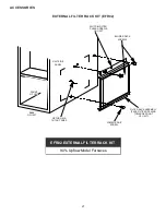
HIGH ALTITUDE INSTALLATION
When this furnace is installed at high altitude, the
appropriate High Altitude Kit including orifices and a
pressure switch(s) must be installed. These changes are
necessary to compensate for the natural reduction in the
density of both the gas fuel and the combustion air at
higher altitude.
Installation of this furnace at altitudes above 7000 ft (2134
m), shall be made in accordance with the Listed High
Altitude Conversion Kit available with this furnace.
Do not derate the furnace by adjusting the manifold
pressure to a lower pressure than specified on the furnace
rating plate. The combination of the lower air density and a
lower manifold pressure will prohibit the burner orifice from
drawing the proper amount of air into the burner. This may
cause incomplete combustion, flashback, and yellow tipping.
In some areas the gas supplier may artificially derate the gas
in an effort to compensate for the effects of altitude. If the
gas is artificially derated, the appropriate orifice size must be
determined based upon the BTU/ft3 content of the derated
gas and the altitude. Refer to the National Fuel Gas Code,
NFPA 54/ANSI Z223.1, and information provided by the
gas supplier to determine the proper orifice size. A different
pressure switch may be required at high altitude regardless
of the BTU/ft3 content of the fuel used. Consult the furnace
Specification Sheet. All conversions must be performed by a
qualified installer, or service agency.
Propane Gas Conversion
This furnace is shipped from the factory configured for
natural gas at standard altitude. To operate this furnace
on L.P. gas, a LPM-07 LP Conversion kit must be used.
Propane gas installations require an orifice and spring
change to compensate for the energy content difference
between natural and propane gas.
For furnaces being converted to LP gas, it is strongly
recommended that a LPLP03 kit also be installed. The
use of this kit will prevent the furnace from firing when
the LP gas supply pressure is too low to support proper
combustion.
All conversions must be performed by a qualified installer,
or service agency.
Gas Valve
This unit is equipped with a 24 volt gas valve controlled
during furnace operation by the integrated control
module. As shipped, the valve is configured for natural
gas. The valve is field convertible for use with propane
gas by replacing the regulator spring with a propane gas
spring from an appropriate manufacturer’s propane gas
conversion kit. Taps for measuring the gas supply pressure
and manifold pressure are provided on the valve.
The gas valve has a manual ON/OFF control located on
the valve itself. This control may be set only to the “ON”
or “OFF” position. Refer to the lighting instructions label
or Startup Procedure & Adjustment for use of this control
during start up and shut down periods.
Gas Piping Connections
The gas piping supplying the furnace must be properly
sized based on the gas flow required, specific gravity of the
gas, and length of the run. The gas line installation must
comply with local codes, or in their absence, with the latest
edition of the National Fuel Gas Code, NFPA 54/ANSI
Z223.1 or CAN/CSA B149.1-15 in Canada.
To connect the furnace to the building’s gas piping, the
installer must supply a ground joint union, drip leg, manual
shutoff valve, and line and fittings to connect to gas valve.
In some cases, the installer may also need to supply a
transition piece from 1/2” pipe to a larger pipe size.
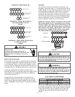
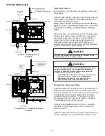
The following stipulations apply when connecting gas
piping. Refer to
Gas Piping Connections
figure for typical
gas line connections to the furnace.
•
Gas piping must be supported external to the furnace
cabinet so that the weight of the gas line does not
distort the burner rack, manifold or gas valve.
•
Use black iron or steel pipe and fittings for building
piping. Where possible, use new pipe that is properly
chamfered, reamed, and free of burrs and chips. If old
pipe is used, be sure it is clean and free of rust, scale,
burrs, chips, and old pipe joint compound.
•
Use pipe joint compound on male threads ONLY.
Always use pipe joint compound (pipe dope) that
is APPROVED FOR ALL GASES. DO NOT apply
compound to the first two threads.
•
Use ground joint unions.
•
Install a drip leg to trap dirt and moisture before it can
enter the gas valve. The drip leg must be a minimum
of three inches long.
•
Install a 1/8” NPT pipe plug fitting, accessible for test
gauge connection, immediately upstream of the gas
supply connection to the furnace.
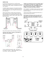
SYSTEM OPERATION


