37
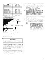
Air cleaner installation location Maximum Heating Airflow Filter (Media) Dimensions Part Number
Air
Cleaner
Family
Si de or bottom return
1200 CFM
16 i n X 20 i n x 5¼"
AM11-1620-5
Si de or bottom return
1600 CFM
16 i n X 25 i n x 5¼"
AM11-1625-5
Si de or bottom return
1600 CFM
20 i n X 20 i n x 5¼"
AM11-2020-5
Si de or bottom return
2000 CFM
20 i n X 25 i n x 5¼"
AM11-2025-5
Si de return
(for 2 s epara te returns)
Si de return (Ri ght a ngle)
2000 CFM
20 i n X 25 i n x 5¼"
AM11-2025-5RA AM11-5RA
Bottom return (pl a tform)
2000 CFM
20 i n X 25 i n x 5¼"
AM11-2832-5PP
Bottom return (pl a tform)
2000 CFM
20 i n X 25 i n x 5¼"
AM11-2843-5PP
AM11-5
2 X 1600 CFM
2, 16 i n X 25 i n x 5¼"
AM11-3225-5
AM11-3225
AM11-5PP
AM11-5
AM11-5RA
AM11-5PP
Family
Family
Family
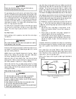
On upflow units, guide dimples locate the side return cutout
locations. Use a straight edge to scribe lines connecting the
dimples. Cut out the opening on these lines.
NOTE:
An under-
sized opening will cause reduced airflow.
Refer to the Filter Sizing Chart to determine filter area re-
quirements.
Change filters before occupants take ownership of a
new home!
U
PRIGHT
I
NSTALLATIONS
Depending on the installation and/or customer preference,
differing filter arrangements can be applied. Filters can be
installed in the central return register or a side panel exter-
nal filter rack kit (upflows). As an alternative a media air
filter or electronic air cleaner can be used as the requested
filter.
FI
L
T
E
R
AIR FLOW
CENTRAL
RETURN
GRILLE
FI
L
T
E
R
SIDE RETURN
EXTERNAL FILTER
RACK KIT
(EITHER SIDE)
Possible Upright Upflow Filter Locations
Figure 43


