41
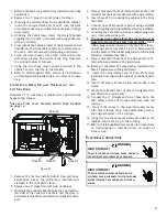
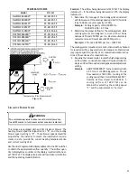
Figure 50A
Outlet
Pressure
Tap
1/8 NPT
Figure 50B
Honeywell Model VR9205R Connected to Manometer
1. Turn OFF gas to furnace at the manual gas shutoff valve
external to the furnace.
2. Connect a calibrated water manometer (or appropriate
gas pressure gauge) at either the gas valve inlet
pressure tap or the gas piping drip leg. See Honeywell
VR9205R gas valve figure for location of inlet
pressure tap.
NOTE:
If measuring gas pressure at the drip leg or Honeywell
VR9205R gas valve, a field-supplied hose barb fitting must be
installed prior to making the hose connection.
3. Turn ON the gas supply, check for leaks and operate
the furnace and all other gas consuming appliances
on the same gas supply line.
NOTE:
To bring furnace up to High Fire, see
instructions for field test mode in
GAS MANIFOLD
PRESSURE MEASUREMENT section.
4. Measure furnace gas supply pressure with burners firing.
Supply pressure must be within the range specified in
the
Inlet Gas Supply Pressure
table.
Natural Gas
Minimum: 4.5" w.c.
Maximum: 10.0" w.c.
Propane Gas
Minimum: 11.0" w.c.
Maximum: 13.0" w.c.
Inlet Gas Supply Pressure
If supply pressure differs from table, make the necessary ad-
justments to pressure regulator, gas piping size, etc., and/or
consult with local gas utility.
5. Turn OFF gas to furnace at the manual shutoff valve
and disconnect manometer. Reinstall threaded plug
before turning on gas to furnace.
6. Turn OFF any unnecessary gas appliances stated in step
3.
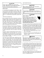
Gas Line
Gas
Shutoff
Valve
Gas Line
To Furnace
Drip Leg Cap
With Fitting
Manometer Hose
Manometer
Open To
Atmosphere
Measuring Inlet Gas Pressure (Alt. Method)
Figure 51
G
AS
M
ANIFOLD
P
RESSURE
M
EASUREMENT
CAUTION
T
O
PREVENT
UNRELIABLE
OPERATION
OR
EQUIPMENT
DAMAGE
,
THE
INLET
GAS
SUPPLY
PRESSURE
MUST
BE
AS
SPECIFIED
ON
THE
UNIT
RATING
PLATE
WITH
ALL
OTHER
HOUSEHOLD
GAS
FIRED
APPLIANCES
OPERATING
.
The manifold pressure must be measured with the burners
operating. To measure the manifold pressure, use the fol-
lowing procedure:
1. Turn OFF gas to furnace at the manual gas shutoff valve
external to the furnace.
2. Turn off all electrical power to the system.
3. Outlet pressure tap connections: Remove the outlet
pressure tap plug. Install an 1/8" NPT hose barb fitting
into the outlet pressure tap. Refer to gas valve
diagram on preceding page.
4. Attach a hose and manometer to the outlet pressure
barb fitting.
5. Turn ON the gas supply.
6. Turn on power and close thermostat “R” and “W1”
contacts to provide a call for low stage heat.
7. Modulating furnaces light at 80% of max input. For
natural gas, the expected manifold pressure at
ignition will be in a range of 1.8” - 2.5” W.C. For LP
gas, the range will be 5.8” - 6.8” W.C.
NOTE:
Measure the gas manifold pressure with the
burners firing. After every time the main power is
turned off and back on, the furnace will enter a
calibration routine on the next call for heat
The
inducer will ramp up and down during the
calibration routine. After calibration, the furnace
will proceed to ignition cycle.

