


43
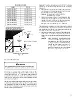
Model
HI / LO
DM97MC0603BN**
20-50/25-55
DM97MC0803BN**
30-60/25-55
DM97MC0804CN**
25-55/25-55
DM97MC1005CN**
35-65/25-55
DM97MC1205DN**
35-65/30-60
DC97MC0603BN**
35-65/30-60
DC97MC0803BN**
35-65/35-65
DC97MC0804CN**
35-65/35-65
DC97MC1005CN**
35-65/30-60
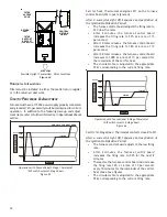
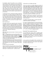
TEMPERATURE RISE
SUPPLY
AIR
RETURN
AIR
Temperature Rise Measurement
Figure 52
C
IRCULATOR
B
LOWER
S
PEEDS
WARNING
T
O
AVOID
PERSONAL
INJURY
OR
DEATH
DUE
TO
ELECTRICAL
SHOCK
,
TURN
OFF
POWER
TO
THE
FURNACE
BEFORE
CHANGING
SPEED
TAPS
.
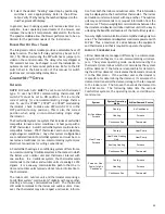
This furnace is equipped with an ECM circulator blower. The
heating blower speed is shipped set at “B”, and the cooling
blower speed setting is “D”. These blower speeds should be
adjusted by the installer to match the installation require-
ments so as to provide the correct heating temperature rise
and correct cooling CFM.
Use the dual 7-segment LED display adjacent to the DIP switches
to obtain the approximate airflow quantity. The airflow quan-
tity is displayed as a number on the display, rounded to the near-
est 100 CFM. The display alternates airflow delivery indication
and the operating mode indication.
Example:
The airflow being delivered is 1225 CFM. The display
indicates 12. If the airflow being delivered is 1275, the display
indicates 13.
1. Determine the tonnage of the cooling system installed
with the furnace. If the cooling capacity is in BTU/hr divide
it by 12,000 to convert capacity to TONs.
Example:
Cooling Capacity of 30,000 BTU/hr.
30,000/12,000 = 2.5 Tons
2. Determine the proper air flow for the cooling system. Most
cooling systems are designed to work with air flows
between 350 and 450 CFM per ton. Most manufacturers
recommend an air flow of about 400 CFM per ton.
Example:
2.5 tons X 400 CFM per ton = 1000 CFM
The cooling system manufacturer’s instructions must be checked
for required air flow. Any electronic air cleaners or other devices
may require specific quantity of air, consult installation instruc-
tions of those devices for requirements.
3. Knowing the furnace model, locate the high stage cooling
air flow table. Look up the cooling air flow determined in
step 2 and find the required cooling speed and adjustment
setting.
Example:
A DM97MC0603BN** furnace installed with
a 2.5 ton air conditioning system. The air
flow needed is 1000 CFM. Looking at the
cooling speed chart for DM97MC0603BN**,
find the air flow closest to 1000 CFM. A
cooling airflow of 1000 CFM can be
attained by selecting the cooling speed
“C” and the adjustment to “normal”.


