background image

4

P

OSSIBLE


PROPERTY


DAMAGE

PERSONAL


INJURY


OR


DEATH


DUE


TO


FIRE

EXPLOSION

SMOKE

SOOT

CONDENSATION

ELECTRICAL


SHOCK


OR


CARBON


MONOXIDE


MAY


RESULT


FROM


IMPROPER


INSTALLATION

REPAIR


OPERATION

OR


MAINTENANCE


OF


THIS


PRODUCT

.

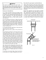
WARNING

S

HOULD


OVERHEATING


OCCUR


OR


THE


GAS


SUPPLY


FAIL


TO


SHUT


OFF

TURN


OFF


THE


MANUAL


GAS


SHUTOFF


VALVE


EXTERNAL


TO


THE


FURNACE


BEFORE


TURNING


OFF


THE


ELECTRICAL


SUPPLY

.

WARNING

S

HIPPING

 I

NSPECTION

All units are securely packed in shipping containers tested
according to International Safe Transit Association specifica-
tions.  The carton must be checked upon arrival for external
damage.  If damage is found, a request for inspection by
carrier’s agent must be made in writing immediately.

The furnace must be carefully inspected on arrival for dam-
age and bolts or screws which may have come loose in tran-
sit.  In the event of damage the consignee should:

1. Make a notation on delivery receipt of any visible

damage to shipment or container.

2. Notify carrier promptly and request an inspection.
3. With concealed damage, carrier must be notified

as soon as possible -  preferably within five days.

4. File the claim with the following support documents

within a nine month statute of limitations.

Original or certified copy of the Bill of Lading, or
indemnity bond.

Original paid freight bill or indemnity in lieu thereof.

B10259-216

CO can cause serious illness including permanent brain

damage or death.

Advertencia especial para la instalación de calentadores ó manejadoras 
de aire en áreas cerradas como estacionamientos ó cuartos de servicio.

B10259-216

El monóxido de carbono puede causar enfermedades severas 
como  daño cerebral permanente ó muerte.

Las emisiones de monóxido de carbono pueden circular a través
del aparato cuando se opera en cualquier modo. 

B10259-216

RISQUE D'EMPOISONNEMENT AU MONOXYDE DE CARBONE

Le monoxyde de 
des 

carbone peut causer des maladies graves telles que

dommages permanents au cerveau et meme la mort.

Cette ventilation est nécessaire pour éviter le danger d'intoxication
au CO pouvant survenir si un appareil produisant du monoxyde 
de carbone continue de fonctionner au sein de la zone confinée.

Original or certified copy of the invoice, showing trade
and other discounts or reductions.

Copy of the inspection report issued by carrier’s
representative at the time damage is reported to
carrier.

The carrier is responsible for making prompt inspection of
damage and for a thorough investigation of each claim. The
distributor or manufacturer will not accept claims from deal-
ers for transportation damage.

E

LECTROSTATIC

 D

ISCHARGE

 (ESD) P

RECAUTIONS

NOTE:

  Discharge your body’s static electricity before touch-

ing unit.  An electrostatic discharge can adversely affect elec-
trical components.

Use the following precautions during furnace installation and

servicing to protect the integrated control module from dam-

age.  By putting the furnace, the control, and the person at

the same electrostatic potential, these steps will help avoid

exposing the integrated control module to electrostatic dis-

charge.  This procedure is applicable to both installed and
non-installed (ungrounded) furnaces.

1. Disconnect all power to the furnace.  Do not touch the

integrated control module or any wire connected to
the control prior  to discharging your body’s electrostatic
charge to ground.

2. Firmly touch a clean, unpainted, metal surface of the

furnaces near the control.  Any tools held in a  person’s
hand during grounding will be discharged.

Summary of Contents for DC97MC

Page 1: ...nuing commitment to quality products may mean a change in specifications without notice 2014 2017 5151 San Felipe St Suite 500 Houston TX 77056 www daikincomfort com SAFETY CONSIDERATIONS 3 SHIPPING I...

Page 2: ...8 STARTUP PROCEDURE ADJUSTMENT 38 HEATING OPERATION WITH CTK01 THERMOSTAT COMMUNICATING 39 HEATING OPERATION WITH CTK02 CTK03 CTK04 THERMOSTAT MODULATING COMMUNICATING 39 CONDENSATE DRAIN TRAP PRIMING...

Page 3: ...ER OPERATION OR DAMAGE TO EQUIPMENT IF THE FURNACE ENVIRONMENT HAS THE POTENTIAL OF FREEZING THE DRAIN TRAP AND DRAIN LINE MUST BE PROTECTED THE USE OF ACCESSORY DRAIN TRAP HEATERS ELECTRIC HEAT TAPE...

Page 4: ...da o cerebral permanente muerte Las emisiones de mon xido de carbono pueden circular a trav s del aparato cuando se opera en cualquier modo B10259 216 RISQUE D EMPOISONNEMENT AU MONOXYDE DE CARBONE Le...

Page 5: ...ly of thermostat kits allow this furnace to be installed as part of a digitally communicating system The ComfortNet system provides advanced airflow configuration enhanced setup features and enhanced...

Page 6: ...nd venting are verified by a qualified person according to these installation instructions Furnace doors must be in place on the furnace while the furnace is operating in any mode Damage or repairs du...

Page 7: ...ng the furnace is between 55 F and 100 F when the furnace is heating Provide provisions for venting combustion products outdoors through a proper venting system Special consideration should be given t...

Page 8: ...w Installation over a combustible floor If installation over a combustible floor becomes necessary use an accessory subbase see Specification Sheet applicable for your model for details Aspecial acces...

Page 9: ...Code CSA B149 1 15 9 After it has been determined that each appliance con nected to the venting system properly vents when tested as outlined above return doors windows ex haust fans fireplace dampers...

Page 10: ...dforallapplianceslocatedwithinthespace Rooms communicating directly with the space in which the appliances are installed throughopeningsnotfurnishedwithdoors andthroughcombustionairopen ings sized and...

Page 11: ...ugh Horizontal Ducts 9 3 3 2 One Permanent Opening Method One permanent openings commencing within 12 in 300 mm of the top of the enclosure shall be provided The appliance shall have clearances of at...

Page 12: ...main burner ignition and during main burner operation Means shall be provided to pre ventthemainburnerformignitingshouldthelouverfailtoopenduringburner startup and to shut down the main burner if the...

Page 13: ...tall on top collector box port 3 Locate 24 x 1 4 tube in bag assembly 4 Install one end on front cover pressure switch 5 Route tube to lower port on collector box cover and cut off excess tubing DRAIN...

Page 14: ...olingthemtothepointwherecondensation takes place Because of the relatively low flue gas temperature and water condensation requirements PVC or ABS pipe is typi cally used as venting and intake pipe ma...

Page 15: ...be CSA listed Solvent cement for ABS to ABS joints must meet ASTM D2235 and if used in Canada must be CSA listed The solvent cement for the PVC to ABS transition joint must meet ASTM D3138 Fittings mu...

Page 16: ...pment The combustion air intake termination of a direct vent application should not terminate in an area which is frequentlydustyordirty NOTE In Canada the current edition of CAN CSA B149 1 15 takes p...

Page 17: ...echanical air supply inlet to building or the combustion air inlet to any other appliance 6 in 15 cm for appliances 10 000 Btuh 3 kW 12 in 30 cm for appliances 10 000 Btuh 3kW and 100 000 Btuh 30 kW 3...

Page 18: ...rnace blower compartment The com bustion air intake pipe can also be secured directly to the coun terflow unit air intake pipe coupling COMBUSTION AIR INTAKE OPTIONS The RF000142 coupling can be secur...

Page 19: ...2 secure with clamps 7 Secure flange to cabinet using screws removed in step 1 Figure 12 Floor Use alternate vent combination air locations DOWN VENTING UPFLOW MODEL FURNACES ONLY Basement Crawlspace...

Page 20: ...NA DM97MC1005CNA DM97MC1205DNA DC97MC0603BNA DC97MC0803BNA DC97MC0804CNA DM97MC0803BNA Direct Vent 2 Pipe and Non Direct Vent 1 Pipe 6 Model Pipe Size Number of Elbows DM97MC0603BNA 1 Maximum allowabl...

Page 21: ...ions Dual Pipe Center to center 10 min 24 max Vertical separation 0 24 Vent termination from wall 8 min 12 max Combustion air intake from wall 6 max Vent and intake clearance to ground or anticipated...

Page 22: ...codes The drain line between furnace and drain location must maintain a 1 4 inch per foot downward slope toward the drain Do not trap the drain line in any other location than at the drain trap suppl...

Page 23: ...e outside of the cabinet barbed end goes in the cabinet through hole in the right side of the cabinet and secure with two field supplied 8 self tapping screws see Figure 22 2 Locate the long drain hos...

Page 24: ...urnace trap UPFLOW MODEL INSTALLED HORIZONTALLY WITH LEFT SIDE DOWN Minimum 5 1 2 clearance is required for the drain trap beneath the furnace Also see Front Cover Pressure Switch Tube Location on pag...

Page 25: ...Insert 100 degree elbow in the cut end of hose 5 7 Locate hose 6 Using red clamps connect between the coupling and 100 degree elbow cutting off excess tubing 8 Draining the Collector Box Remove cap fr...

Page 26: ...may exit the right or left side of the fur nace cabinet left side preferred Trap and factory installed hoses remain as shipped if the drain will exit the left side of the cabinet Draining from the rig...

Page 27: ...lector box drain port and secure with a silver clamp 5 Insert hose 2 from outside the cabinet in the front drain hole 6 Connect hose 4 hose 2 together using a straight barbed coupling and two gold cla...

Page 28: ...cated to the other side of the burner compartment prior to making electrical connections To relocate the junction box follow the steps shown below NOTE Wire routing must not interfere with circulator...

Page 29: ...t or left side panel Thermostat wiring entrance holes are lo cated in the blower compartment The following figure shows connections for a heat cool system This furnace is equipped with a 40 VA transfo...

Page 30: ...ace Toenablethedehumidifyfunctionontheintegratedcontrolmod ule set the dehumidification ENABLE DIP switch from OFF to ON Oncetheswitchisset thedehumidifyfunctionisenabledduring a combination call for...

Page 31: ...eded to prevent unit overfiring Natural Gas Minimum 4 5 w c Maximum 10 0 w c Propane Gas Minimum 11 0 w c Maximum 13 0 w c Inlet Gas Supply Pressure A heat pump thermostat with three stages of heat is...

Page 32: ...ps If old pipe is used be sure it is clean and free of rust scale burrs chips and old pipe joint compound Use pipe joint compound on male threads ONLY Always use pipe joint compound pipe dope that is...

Page 33: ...s Line Hole Ground Joint Pipe Union Ground Joint Pipe Union NOTE Union may be inside furnace cabinet where allowed by local codes COUNTERFLOW Figure 37 Manual Shut Off Valve upstream from ground joint...

Page 34: ...CTING WARNING DEVICE IN CASE OF A GAS LEAK SINCE PROPANE GAS IS HEAVIER THAN AIR ANY LEAKING GAS CAN SETTLE IN ANY LOW AREAS OR CONFINED SPACES PROPANE GAS ODORANT MAY FADE MAKING THE GAS UNDETECTABLE...

Page 35: ...hich can cause excessive temperature rise This can cause limit switch tripping and heat exchanger fail ure To determine total external duct static pressure proceed as follows 1 With clean filters in t...

Page 36: ...st be provided sized and installed externally by the installer Filters must comply with UL900 or CAN ULCS111 standards Damage or repairs due to the installa tion of the furnace without filters are not...

Page 37: ...11 5 AM11 5RA AM11 5PP Family Family Family On upflow units guide dimples locate the side return cutout locations Use a straight edge to scribe lines connecting the dimples Cut out the opening on thes...

Page 38: ...g rate to 35 low fire rate After 2 minutes the furnace control board increases the firing rate to 57 at a rate of 1 per second After 10 total minutes the furnace control board increases the firing rat...

Page 39: ...ompatible with a CTK01 communicating thermostat When a call for heat is sent the furnace will go through the Light Off Sequence at which time the Heat Current Demand Status will still show 0 After the...

Page 40: ...rnace gas valve manual control to the ON position 8 Replace the burner compartment door 9 Open the manual gas shutoff valve external to the furnace 10 Turn on the electrical power to the furnace 11 Ad...

Page 41: ...Turn OFF any unnecessary gas appliances stated in step 3 Gas Line Gas Shutoff Valve Gas Line To Furnace Drip Leg Cap With Fitting Manometer Hose Manometer Open To Atmosphere Measuring Inlet Gas Press...

Page 42: ...uring the smallest quantity usually the dial that indicates 1 2 cu ft per revolution You will use this number to calculate the quantity of gas in cubic ft if the furnace would consume if it ran steadi...

Page 43: ...flow being delivered is 1225 CFM The display indicates 12 If the airflow being delivered is 1275 the display indicates 13 1 Determine the tonnage of the cooling system installed withthefurnace Iftheco...

Page 44: ...Verify CFM by noting the number displayed on the dual 7 segment LED display 6 The multi speed circulator blower also offers several custom ON OFF ramping profiles for cooling These profiles may be use...

Page 45: ...one another In a traditional system the thermostat sends commands to the indoor and outdoor units via analog 24 VAC signals It is a one way communication path in that the in door and outdoor units ty...

Page 46: ...Net wiring will consist of four wires between theindoorunitandoutdoorunitandbetweentheindoorunitand thermostat The required wires are a data lines 1 and 2 b thermostat R 24 VAC hot and C 24 VAC common...

Page 47: ...econds ON ON 1 Stage Stat OFF 2 Stage Stat ON 1 Stage Compressor OFF 2 Stage Compressor ON Disabled OFF Enabled ON Disabled OFF Enabled ON Disabled OFF Enabled ON Disabled OFF Enabled ON Not applicabl...

Page 48: ...ncluded in CTK01 kit 208 230 VAC 24 VAC 1 2 R C System Wiring using Two Wires between Furnace and AC HP and Four Wires between Furnace and Thermostat 1 2 R C C Y ComfortNet Compatible Furnace Integrat...

Page 49: ...om most recent to least recent A Maximum of 3 consecutive faults of the same type will be logged Each error is displayed for 2 seconds with a blank screen for 1 second in between When all errors have...

Page 50: ...or are energized to their appropriate speed Circulator blower is energized on the appropriate cool speed at the level and time determined by the selected ramping profile Electronic air cleaner termina...

Page 51: ...or 100 DIP switch selectable when using a conventional thermostat Electronic air cleaner terminal is energized The furnace control board HUM dry contacts close Circulator blower runs integrated contr...

Page 52: ...ls held in a person s hand during grounding will be discharged 3 Service integrated control module or connecting wiring following the discharge process in step 2 Use caution not to recharge your body...

Page 53: ...n the installation differing filter arrangements can be applied Filters can be installed in either the central return register or a side panel external filter rack upflow only Ame dia air filter or el...

Page 54: ...r s Manual with the homeowner and discuss proper furnace operation and maintenance Leave literature packet near furnace REPAIR AND REPLACEMENT PARTS When ordering any of the listed functional parts be...

Page 55: ...stage pressure switch circuit is closed at start of heating cycle PS1 CLOSED E1 Low stage pressure switch contacts sticking Shorts in pressure switch circuit wiring Replace low stage pressure switch...

Page 56: ...ace o peratio n Integrated co ntro l m o dule LED display pro vides E 5 erro r co de Co mfo rtNet thermo stat displays B attery P o wer E5 Open Fuse No t Displayed No t Displaye d Sho rt in lo w vo lt...

Page 57: ...t thermostat Call for Service icon illuminated ComfortNet thermostat scrolls Check Furnace message EA Polarity of 1 1 5 volt AC is reversed REVERSED PLTY EA Polarity of 1 1 5 volt AC power to furnace...

Page 58: ...a set in integrated control module Verify circulator blower motor horse power is the same specified for the specific furnace model Replace if necessary Verify shared data set is correct for the specif...

Page 59: ...ct Description and Location Requirements Considerations for furnace installation requirements Turn power OFF prior to repair Furnace fails to operate Integrated control module LED display provides b7...

Page 60: ...MORY CARD DATA dF DEFROST DEMAND E0 LOCKOUT DUE TO EXCESSIVE RETRIES OR RECYCLES E1 LOW STAGE PRESSURE SWITCH STUCK CLOSED AT START OF HEATING CYCLE E2 LOW STAGE PRESSURE SWITCH STUCK OPEN E3 OPEN HIG...

Page 61: ...ING TO UNIT MUST BE TO UNIT MUST BE PROPERLY POLARIZED EQUIPMENT GND FIELD SPLICE SWITCH TEMP SWITCH PRESSURE PROT DEVICE LOW VOLTAGE FIELD LOW VOLTAGE 24V HI VOLTAGE 115V HI VOLTAGE FIELD INTERNAL TO...

Page 62: ...e no less than one half 1 2 inch in size GAS VENT DIRECTLY BELOW KEEP CLEAR OF ALL OBSTRUCTIONS 4 INSPECTION The state or local gas inspector of the side wall horizontally vented gas fueled equipment...

Page 63: ...63 THIS PAGE LEFT INTENTIONALLY BLANK...

Page 64: ...NCE DATA LISTED HEREIN ARE SUBJECT TO CHANGE WITHOUT NOTICE Our continuing commitment to quality products may mean a change in specifications without notice 2014 2017 5151 San Felipe St Suite 500 Hous...

Reviews: