IM 1040 • VAV ACTUATOR
6
www.DaikinApplied.com
s
TarT
-u
p
p
roCedures
Enabling autozero module
CAUTION
If an Autozero Module is used, do not enable MTR3 (valve 2).
NOTICE
For a controller without an Autozero Module, the damper
is commanded closed to get a zero airflow reading during
calibration. For a controller with an Autozero Module, the
damper is closed only for the first calibration after controller
initialization or power up.
If an Autozero Module is used, enable it by setting CAL
MODULE to Y.
Selecting automatic calibration option
NOTICE
The air velocity sensor must be calibrated at least once every
24 hours. Make sure that the sensor has been calibrated
before balancing takes place, as this will affect the balancer’s
results.
NOTICE
Options can be combined by summing their numbers. For
example, to calibrate as in Options 1 and 2, set CAL SETUP
to 3.
Using
Table 5
set CAL SETUP to the value that best meets
your job requirements.
If appropriate, change CAL TIMER from the default of 12
hours. This setting applies only if your choice for CAL SETUP
includes Option 4.
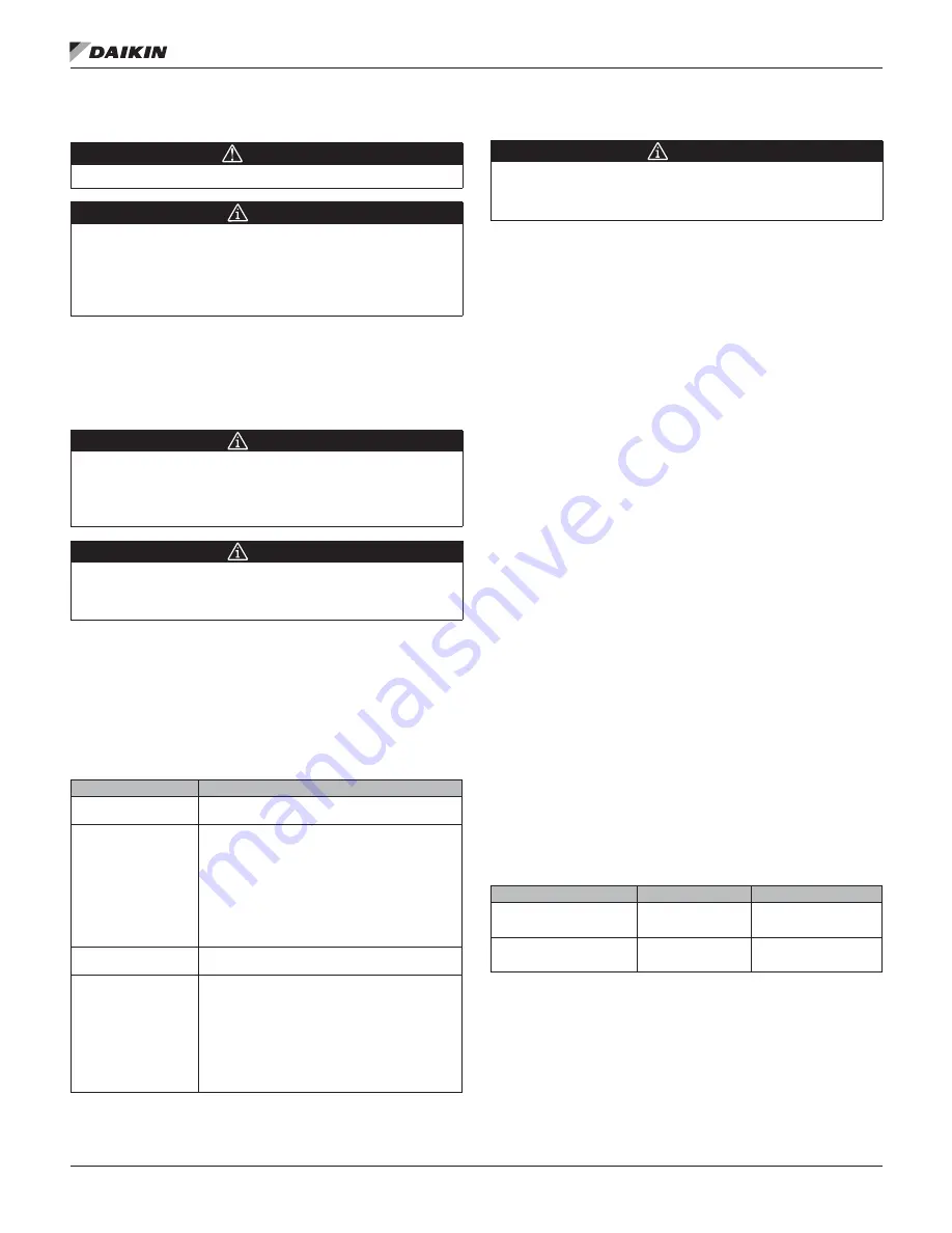
Table 5: CAL SETUP Values
CAL SETUP (Point 95)
Description
0
Calibration occurs ONLY when the point CAL AIR
(Point 94) is set to YES
1
Calibration occurs when the field panel commands
a day/night mode changeover. Actual calibration is
subject to a time delay of 0, 1, 2, or 3 minutes. This
delay is determined by the point CTLR ADDRESS
(Point 1) divided by 4. The remainder is the time
delay in minutes.
Example: If CTLR ADDRESS = 11, then the
controller will wait 3 minutes (11 ÷ 4 = 2 R3) after it
receives the day/night mode changeover command
before beginning the calibration routine.
2
Calibration occurs immediately after the override
switch is depressed.
4
(factory default value)
Calibration occurs on the time interval set in the
point CAL TIMER (Point 96).
For example, if CAL TIMER = 12, then the
calibration period is12 hours. Actual calibration is
subject to a time delay based on the value of CTLR
ADDRESS.
See the example in Option 1. This is the
recommended option when using a controller with
an Autozero Module.
Setting room temperature setpoints
NOTICE
If STPT DIAL is set to YES, do not set the DAY (or OCC)
setpoints; the value of RM STPT DIAL will be used for these
points.
•
DAY (or OCC) cooling setpoint
•
DAY (or OCC) heating setpoint
•
NGT (or UOC) cooling setpoint
•
NGT (or UOC) heating setpoint
If the room temperature sensor has a setpoint dial that will be
used, set STPT DIAL to YES. Otherwise, set STPT DIAL to NO.
Set the room temperature setpoints to the desired values
(some points are not present in certain cooling only
applications).
Set RM STPT MIN and RM STPT MAX for the minimum and
maximum allowable room temperature setpoints, respectively.
Valid values range from 55°F to 95°F (13°C to 35°C). Default
values are 55°F (13°C) for RM STPT MIN and 90°F (32°C) for
RM STPT MAX.
Setting override time
If using night/unoccupied override, set OVRD TIME to the
number of whole hours that an override should last. If OVRD
TIME equals 0 (default), then this feature is disabled.
Enabling Wall Switch
If a wall switch is used for day/night (Occ/Unocc) control,
enable it by setting WALL SWITCH to YES.
Setting Duct Area
If provided, enter the duct area (sq ft or sq m) into DUCT
AREA (and also into HTGDUCT AREA, where applicable) and
continue to
Setting flow coefficient on page 7
.
If you do not know the duct area, use
Table 6
:
Table 6: Duct Area Calculation
Area =
Round Duct
Rectangular Duct
Area in Sq. Ft.
(Dimensions in inches)
(π x R2)/144
Width × Height/144
Area in Sq. M.
(Dimensions in centimeters)
(π × R2)/10,000
Width × Height/10,000
Summary of Contents for BACnet
Page 9: ......


