


5 Configuration
Installation manual
15
EBLQ+EDLQ011~W1
Daikin Altherma low temperature monobloc
4P522031-1 – 2018.01
INFORMATION
▪ During the copying, both controllers will NOT allow
operation.
▪ The copy operation can take up until 90 minutes.
▪ It is recommended to change installer settings, or the
configuration of the unit, on the main user interface. If
not, it can take up to 5 minutes before these changes
are visible in the menu structure.
8
Your system is now set to be operated by the 2 user interfaces.
5.1.4
To copy the language set from the first to
the second user interface
See
"5.1.3 To copy the system settings from the first to the second
user interface" on page 14
.
5.1.5
Quick wizard: Set the system layout after
first power ON
After first power ON of the system, you are guided on the user
interface to do initial settings:
▪ language,
▪ date,
▪ time,
▪ system layout.
By confirming the system layout, you can proceed with the
installation and commissioning of the system.
1
At power ON, the quick wizard starts as long as the system
layout was NOT confirmed yet, by setting the language.
Language
Select the desired language
Confirm
Adjust
2
Set the current date and time.
00
: 00
What is the current time?
Time
Confirm
Adjust
Scroll
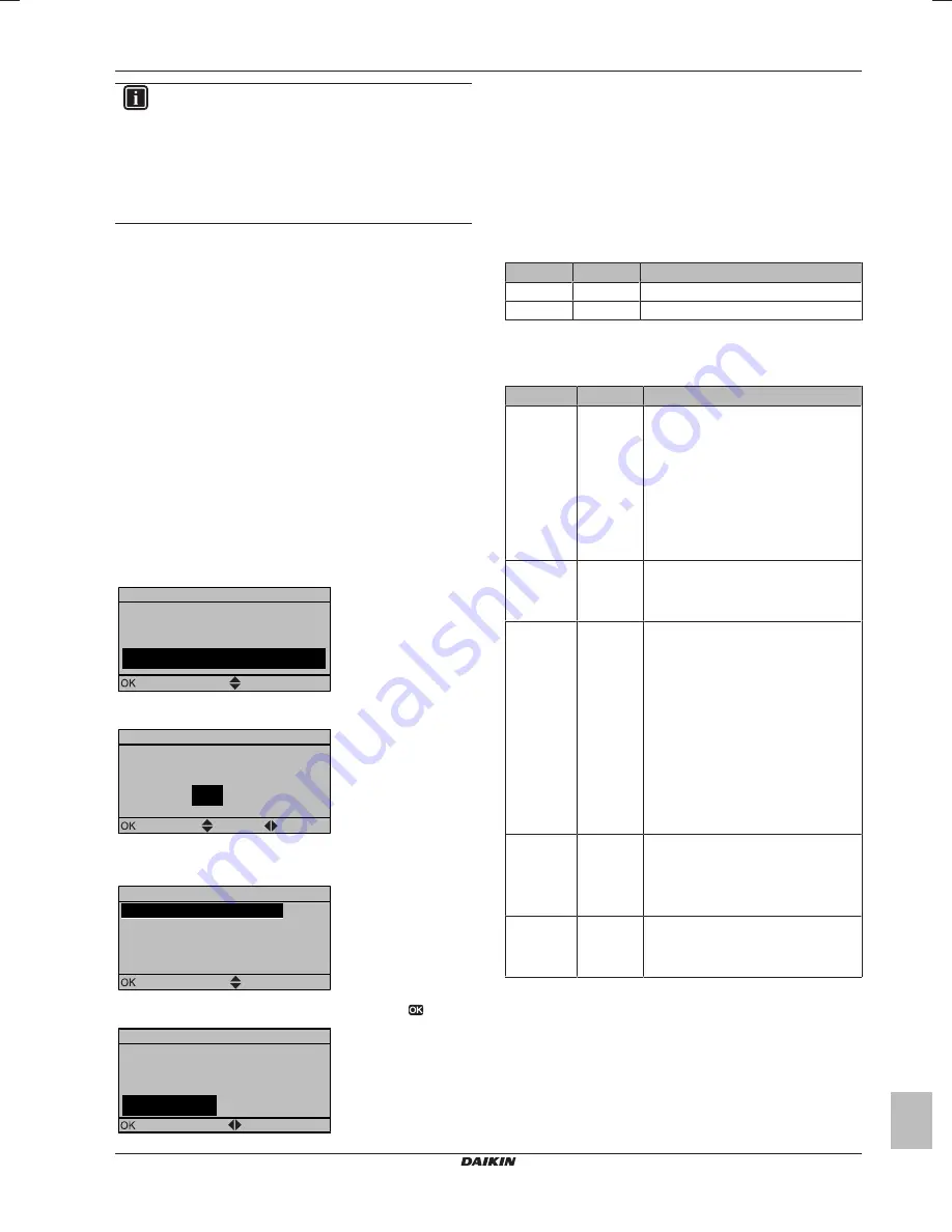
3
Set the system layout settings: Standard, Options, Capacities.
For more details, see
"5.2 Basic configuration" on page 15
.
A.2
1
Scroll
Select
System layout
Standard
Options
Capacities
Confirm layout
4
After configuration, select Confirm layout and press
.
Confirm layout
Please confirm the system
layout. The system will
restart and will be ready for
first startup.
OK
Cancel
Confirm
Adjust
5
The user interface re-initialises and you can proceed the
installation by setting the other applicable settings and
commissioning of the system.
When the installer settings are changed, the system will request to
confirm. When confirmation is complete, the screen will shortly turn
OFF and "busy" will be displayed for several seconds.
5.2
Basic configuration
5.2.1
Quick wizard: Language / time and date
#
Code
Description
[A.1]
N/A
Language
[1]
N/A
Time and date
5.2.2
Quick wizard: Standard
Space heating/cooling settings
#
Code
Description
[A.2.1.7]
[C-07]
Unit temperature control:
▪ 0 (LWT control): Unit operation is
decided based on the leaving water
temperature.
▪ 1 (Ext RT control): Unit operation is
decided by the external thermostat.
▪ 2 (RT control): Unit operation is
decided
based
on
the
ambient
temperature of the user interface.
[A.2.1.8]
[7-02]
Number of water temperature zones:
▪ 0 (1 LWT zone): Main
▪ 1 (2 LWT zones): Main + additional
[A.2.1.9]
[F-0D]
Pump operation:
▪ 0 (Continuous): Continuous pump
operation, regardless of thermo ON or
OFF condition.
▪ 1 (Sample): When thermo OFF
condition occurs, the pump runs every
5 minutes and the water temperature
is checked. If the water temperature is
below target, unit operation can start.
▪ 2 (Request)(default): Pump operation
based on request.
Example:
Using a
room
thermostat
and
thermostat
creates thermo ON/OFF condition.
[A.2.1.B]
N/A
Only if there are 2 user interfaces:
User interface location:
▪ 0 (At unit)
▪ 1 (In room)(default)
[A.2.1.C]
[E-0D]
Glycol present:
▪ 0 (No)(default)
▪ 1 (Yes)


