background image


13 


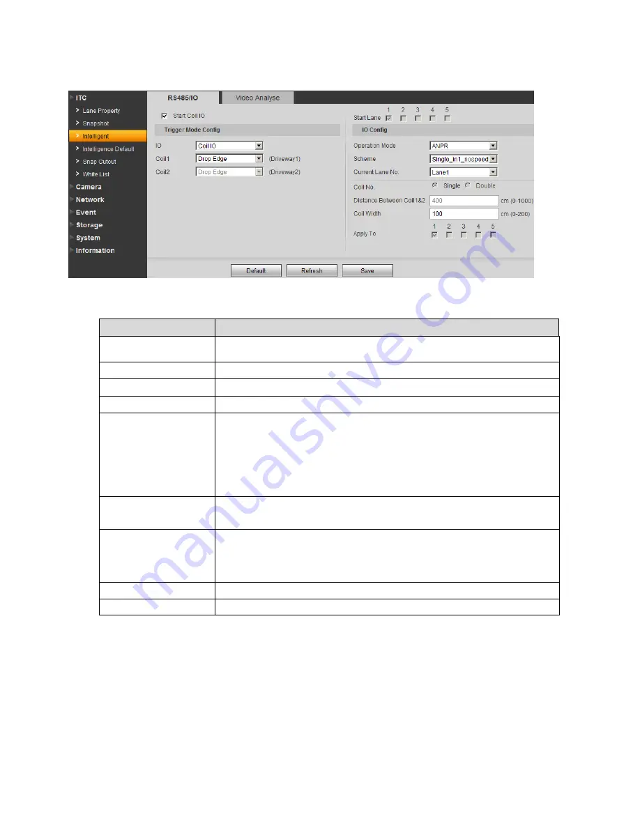
Figure 3-4 RS485/IO 

Please refer to the following sheet for detailed information.  

Parameter 

Note 

Start Coil IO 

Select Start Coil IO enable option, to enable coil IO, may config 
trigger mode and IO. 

IO 

Select coil IO. 

Coil X 

Set each coil’s trigger mode. 

Operation Mode 

Support ANPR mode.  

Scheme 

Include several typical combination of coil snapshot. 
ANOR mode


Double_in2_nospeed

dual  coils,  when  vehicle  head  enters 

the 2

nd

 coil, snapshot 


Single_in1_nospeed

single  coil,  when  vehicle  head  or  tail 

enters the coil, snapshot 

Current Lane No. 

Select different lanes to set corresponding coil parameters.  

Distance Between 
Coil1&Coil2 

Actual distance from centers of coil 1 to coil 2.  
Note: 
This value must match actual value, other speed measurement 
will not be accurate.  

Coil Width 

According to actual condition, set coil width.  

Apply to 

Apply config scheme of current channel to other channels.  

3.1.3.2 Video Analysis 


The video analysis interface is shown as in Figure 3-5. 

Summary of Contents for ITC237-PW1A-IRZ

Page 1: ...i ITC237 PW1A IRZ Web Operation Manual Version 1 0 0 ...

Page 2: ...ansportation 3 Installation Do not apply power to the camera before completing installation Please install the proper power cut off device during the installation connection in case there is any emergency situation Always follow the instruction guide the manufacturer recommended 4 Qualified engineers needed All the examination and repair work should be done by the qualified service engineers We ar...

Page 3: ... all the components are included Contact your local retailer ASAP if something is broken in your package 7 Daily Maintenance Please shut down the device and then unplug the power cable before you begin daily maintenance work Use the dry soft cloth to clean the device If there is too much dust please use the water to dilute the mild detergent first and then use it to clean the device Finally use th...

Page 4: ...Configure 10 3 1 ITC 10 3 1 1 Lane Property 10 3 1 2 Snapshot 11 3 1 3 Intelligence Default 12 3 1 4 Intelligence Default 17 3 1 5 Snap Cutout 17 3 1 6 White List 18 3 2 Camera 20 3 2 1 Attribute 21 3 2 2 Video 23 3 3 Network 28 3 3 1 TCP IP 28 3 3 2 IP Filter 29 3 4 Event 29 3 4 1 Relay out 29 3 4 2 Abnormity 30 3 5 Storage 31 3 6 System 31 3 6 1 General 31 3 6 2 Account 33 3 6 3 Default 38 3 6 4...

Page 5: ...v 3 7 Information 40 3 7 1 Version 40 3 7 2 Log 41 3 7 3 Online User 42 4 Logout 43 ...

Page 6: ...2 168 1 108 then please input http 192 168 1 108 in IE address column See Figure 1 1 Figure 1 1 IE System pops up warning information to ask you whether install webrec cab control or not Please click yes button If you can t download the ActiveX file please modify your settings as follows See Figure 1 2 Input your IP address here ...

Page 7: ...fter installation the interface is shown as below See Figure 1 3 Please input your user name and password Default factory name is admin and password is admin Note For security reasons please modify your password after you first login ...

Page 8: ...3 Figure 1 3 Login Interface After you logged in HD intelligent traffic camera web main interface is shown as in Figure 1 4 Figure 1 4 Web Main Interface ...

Page 9: ...stream to record video record network monitor function under normal network environment You can set resolution within its supported range Extra stream It is a substitute for main stream under insufficient band width Protocol Select video monitoring protocol currently support TCP only 1 3 Preview Window Switch The preview window switch interface is shown as in Figure 1 6 Figure 1 6 Preview Window S...

Page 10: ...up It is to adjust monitor video brightness It is to adjust monitor video contrast It is to adjust monitor video hue It is to adjust monitor video saturation Reset Reset brightness contrast hue and saturation to system default values 1 4 System Menu System menu is shown as in Figure 1 8 Please refer to chapter 1 Live chapter 2 Query chapter 3 Setup chapter 4 Logout for detailed information Figure ...

Page 11: ...shot Snapshots are saved based on setup in Setup Camera Video Path Zoom in Click on the button to zoom in with left mouse Right click to exit Snapshot Click on the button to snapshot current picture and save it Record Click on the button to record Record file is saved based on setup in Setup Camera Video Path Please refer to Chapter 4 2 2 5 Easy Focus Click Easy Focus to auto focus or you can manu...

Page 12: ...7 Display in full screen ...

Page 13: ...s in Figure 2 1 Click Open Local select picture you want to verify and click Water Verify then you can view the result Select the picture click Open to preview Figure 2 1 Picture Query 2 2 Record Query 2 2 1 Record Click record query you can see an interface is shown as in Figure 2 2 ...

Page 14: ...ion he she must enable water mark in Setup Camera Video and set watermark content Default watermark is DigitalCCTV Select record file click Water Mark system shows progress of verifying and normal watermark See Figure 2 3 Figure 2 3 When it is complete the page will show complete ...

Page 15: ...ing sheet for detailed information Parameter Function Snap enable Select lane to enable The no corresponds to actual lane no Working road Select road type Lane Select lane to snapshot Customized lane no Set different no for each lane Direction Select lane direction to snapshot Left lane line type Solid white line by default Right lane line type Solid white line by default Direction Set vehicle dir...

Page 16: ...ure 3 2 Advance Config Parameter Function Snap Amount Set number of snapshot Snap Direction Check Observe to snapshot vehicle driving in correct direction only Check Reserve to snapshot vehicle driving in retrorse direction only Check DoubleDirection to snapshot vehicles in both directions at the same time 3 1 2 Snapshot The snapshot interface is shown as in Figure 3 3 ...

Page 17: ...ax speed supported by device OSD select Set OSD menu General info Select OSD info displayed on picture border Address Set device installation address and this OSD will be displayed on picture border Extend info Select OSD info to be displayed on picture border Font Set OSD info font size color Refresh Click on refresh to receive the latest device parameters 3 1 3 Intelligence Default 3 1 3 1 RS485...

Page 18: ...al coils when vehicle head enters the 2nd coil snapshot Single_in1_nospeed single coil when vehicle head or tail enters the coil snapshot Current Lane No Select different lanes to set corresponding coil parameters Distance Between Coil1 Coil2 Actual distance from centers of coil 1 to coil 2 Note This value must match actual value other speed measurement will not be accurate Coil Width According to...

Page 19: ...ane represents moving direction Select and click on redraw to drawn region You can only draw in up down direction Detect Draw border line to trigger snapshot which is similar to actual coil When vehicle reach this line snapshot will be triggered Detect line is available inside drawn region only Select and click on redraw to drawn region Vehicle head vehicle rear When you select front lane arrow is...

Page 20: ... actual value otherwise speed measure will be inaccurate L1 This is distance from camera to scene bottom Note This value must match actual value otherwise speed measure will be inaccurate L2 This is distance from camera to scene median yellow line Note This value must match actual value otherwise speed measure will be inaccurate The recognition interface is shown as in Figure 3 7 ...

Page 21: ...late Size Set plate Min Height Max Height Min Width Max Width while only Min Width and Max Width are available for use Non motorized vehicle snapshot Select this parameter to snapshot non motorized vehicle Unlicensed motor category Select this parameter to snapshot unlicensed motors Analyse Mode Select recognition mode includes Head Mode Tail Mode Head Prior Mode Tail Prior Mode ...

Page 22: ...fault The intelligence default interface is shown as in Figure 3 9 Click on default to restore default settings Note You cannot restore IP address and other network info Figure 3 9 Intelligence Default 3 1 5 Snap Cutout Check SnapCutoutEnable click Save System will cutout one part from snapshot and save to storage path See Figure 3 10 ...

Page 23: ...d property info 3 In Link Sign Out page enable Traffic Trust List and set alarm signal output delay All open System auto opens for all in out vehicles In Link Sign Out page enable AllSnapCar and set alarm signal output delay Command open If the device has connected to platform send command via the platform to open gate In Link Sign Out page enable Order and set alarm signal output delay Manual ope...

Page 24: ...g function If the snapshot plate does not match white list you can set white list accordingly Plate matching fuzzy search has the same property of plate on white list Note Only when Traffic Trust List is enabled fuzzy match is valid Care Word Select range of plate matching characters Min Length Min number of matched plate characters 3 1 6 2 White List Search The white list search is shown in Figur...

Page 25: ...plate info Clear all Clear all white list data in device 3 1 6 3 Link Sign Out The link sign out interface is shown in Figure 3 13 Figure 3 13 Link Sign Out Parameter Note Enable After check enable gateway control and config Control Type May trigger alarm via different gateway Traffic Trust List snapshot vehicle matching white list or fuzzy match of white list output open gate signal AllSnapCar sn...

Page 26: ...e value adjusts contrast of full image Default value is 50 The higher the value the higher the contrast of image When contrast is insufficient you may adjust this value Recommended value is 40 60 within 0 100 range Hue The value adjusts hue of image Default value is 50 It will not affect image brightness It has a relatively fixed value according to the sensor Recommended value is 40 60 within 0 10...

Page 27: ...Tridim Check ON to enable 3D NR lower noise Sync signal Sync signal Inner sync and outside sync When you select outside sync you can drag slider to set Outside sync precedes AC sync signal Note means current item is used 3 2 1 2 Shutter The shutter interface is shown as in Figure 3 15 Figure 3 15 Shutter Please refer to the following sheet for log parameter information Parameter Function Shutter m...

Page 28: ...face is shown as in Figure 3 16 Figure 3 16 Metering Zone Please refer to the following sheet for log parameter information Parameter Function Measure mode Spot measure For moving vehicle Partial measure For sensitive zone If the zone is bright entire zone will be dark and vice versa Global measure For set sensitive area measure brightness and thus adjust the entire image brightness 3 2 2 Video 3 ...

Page 29: ...e type It includes CBR and VBR Under VBR you can set image quality Bit rate Under VBR this value serves as upper limit Under CBR this value is fixed It is the best range of bit rate I frame interval It is the P frame between two I frame with range1 150 Default is two times frame rate Watermark settings By verifying watermark character you may check if record is edited Check front box to enable fun...

Page 30: ...p General snap works within predetermined time period Trigger snap works at time of motion detect privacy masking and relay activation Note This device does not support this function Pic size Be consistent with main stream resolution Note This device does not support this function Quality Select snap quality from 6 levels Picture coding size Set picture coding size 3 2 2 3 Overlay The overlay inte...

Page 31: ...nable and click on setup to set You may drag time title in window to choose its position Channel title Enable this function to display channel title Enable and click on setup to set You may drag channel title in window to choose its position Font size Set channel and time title font size 3 2 2 4 Interest Area The interest area interface is shown as in Figure 3 20 ...

Page 32: ...ase refer to the following sheet for log parameter information Parameter Function Image quality You may drag left mouse to set interest area Select snap quality from 6 levels 3 2 2 5 Path The path interface is shown as in Figure 3 21 ...

Page 33: ...ctureDownload Record default path is C RecordDownload 3 3 Network 3 3 1 TCP IP The TCP IP interface is shown as in Figure 3 22 Figure 3 22 TCP IP Please refer to the following sheet for log parameter information Parameter Function Host name Set current host name Max supports 32 characters ...

Page 34: ...you must set IP parameters again MAC address Display host MAC address IP version Select IP version IPV4 or IPV6 These two IP addresses both can be accessed IP address Input new IP address to edit and set subnet mask and default gateway Preferred DNS DNS server IP address Alternate DNS DNS server alternate IP address 3 3 2 IP Filter The IP filter interface is shown as in Figure 3 23 You may set tru...

Page 35: ... directly output alarm output signal Refresh View the latest relay out status 3 4 2 Abnormity The abnormity interface is shown as in Figure 3 25 Figure 3 25 Disconnection Please refer to the following sheet for log parameter information Parameter Function Enable Check box to enable this function Relay out When alarm occurs set corresponding relay out You must enable this function first ...

Page 36: ...ends You can set X within 10 s 300 s 3 5 Storage Select FTP as storage then FTP is enabled You can set picture name and path Click Help to view rule of naming The FTP interface is shown as in Figure 3 26 Figure 3 26 Path 3 6 System 3 6 1 General The general interface is shown as in Figure 3 27 ...

Page 37: ...vice name Set device name Language Select language and then close IE When you log in again system language will change Video standard Display device video standard such as PAL Machine Group Input device group Machine Address Input snapshot address of the device The date time interface is shown as in Figure 3 28 ...

Page 38: ...urrent system time Setup becomes effective immediately Sync PC Sync system time with PC time Click on save to refresh system time DST enable Set DST may by date or week Setup becomes effective immediately Synchronize With NTP Check to sync with NTP NTP server Set NTP server address Port Set NTP port no Time zone Set device time zone Update period Set device update period 3 6 2 Account Note ...

Page 39: ...ame and modify user password Figure 3 29 Account Anonymous login Enable anonymous login as input IP without username and password to log in device This type of account only have preview right You may switch to other account by clicking on logout Add user Add user within group and set user right By default there are three users admin 888888 and 666666 Their passwords are the same as corresponding u...

Page 40: ...35 Figure 3 30 Add User Modify user Modify existing user s group password right and note See Figure 3 31 ...

Page 41: ...ers including letter and number only Note You cannot modify right of the logged in account You cannot modify or delete admin 888888 and 666666 accounts Account who has right to modify other account can modify other user account besides its own You cannot delete currently logged in account 3 6 2 2 Group The group interface is shown as in Figure 3 32 Here you can add and delete group and modify grou...

Page 42: ...ight Enter add group interface and input group name select right among given list The add group interface is shown as in Figure 3 33 Figure 3 33 Add Group Modify group Click on modify you may edit group in prompt box The modify group interface is shown as in Figure 3 34 ...

Page 43: ...lete admin and user groups You cannot delete group which contains currently logged in user 3 6 3 Default The default interface is shown as in Figure 3 35 Figure 3 35 Default Note Network IP address cannot be restored to default 3 6 4 Import Export ...

Page 44: ...mport Export Please refer to the following sheet for log parameter information Parameter Function Export Export system config to local Import Import local config to system 3 6 5 Auto Maintain The auto maintains interface is shown as in Figure 3 37 Figure 3 37 Auto Maintain ...

Page 45: ...ive 3 6 6 Upgrade When system upgrades you shall select firmware file Firmware file ends in bin Please maintain stable power supply connection and do not reboot or shut down camera during this process The upgrade interface is shown as in Figure 3 38 Figure 3 38 Upgrade Note If system encounters error during upgrading the device may malfunction 3 7 Information 3 7 1 Version The version interface is...

Page 46: ...ime All info here subject to actual condition 3 7 2 Log The log interface is shown as in Figure 3 40 Figure 3 40 Log Please refer to the following sheet for log parameter information Parameter Function Start time Set start time of log to search End time Set end time of log to search ...

Page 47: ...ll see logs searched out Click on stop to stop log search Detailed info Click on log to view its detailed information Clear Clear all system log displayed You cannot clear log by type Backup Create backup of displayed log onto current used PC 3 7 3 Online User The online user interface is shown as in Figure 3 41 Here displays online user and their group IP address and login time Figure 3 41 Online...

Page 48: ...t difference may be found in the user interface All the designs and software here are subject to change without prior written notice All trademarks and registered trademarks mentioned are the properties of their respective owners If there is any uncertainty or controversy please refer to the final explanation of us Please visit our website or contact your local retailer for more information ...

Reviews: