background image


Network  Settings

    30 


Sheet 4-1 Parameter Description 

No. 

Parameter Description 

Please refer to Sheet 4-2 for more details about the menu column. 
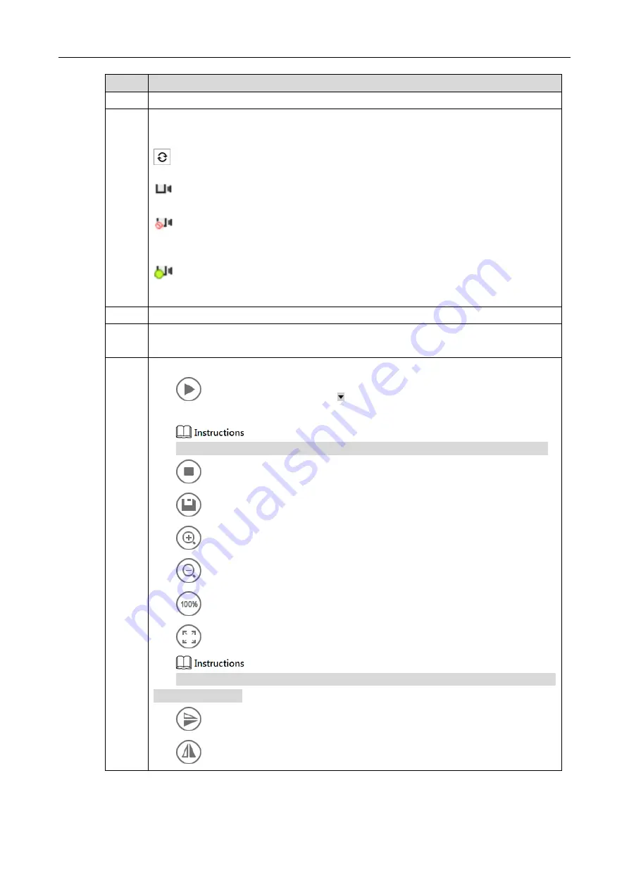
It  is  to  detect  the  device  list  of  all  the  online  devices,  which  are  GigE,  USB  and 

CameraLink. 

Refresh, click the icon and manually refresh the info of online device. 

It means the device is in a connectable state. 

It means the device is in a non-connectable state; please make sure USB3 drive has 

been installed. 

It means the device is in a connected state. MV Viewer can only connect and operate 

one camera. 

It is to select port info and device info displayed by some device. 

The setup info of the current image, which includes video stream, image stream, display 

stream, image location, gray level and RGB color value, etc. 

It is to play the adjustment toolbar of the image. 


Play Button. You can click    according to your needs, and select play mode 

of continuous, single-frame and multi-frame in the drop-down list.   


Only when the image is paused can you switch the play mode in the drop-down list. 


Stop button. 


Save picture. 


Zoom in button; it is to zoom in the display image. 


Zoom out button; it is to zoom out the display image. 


Display the image in 100%. 


Display the video image according to the window size. 


Click the icon to display video image according to the window size when the image 

is zoomed in or out. 


Up and down mirror for the image. 


Left and right mirror for the image. 

Summary of Contents for 3000 Series

Page 1: ...USB3 0 Area Scan Industrial Camera User Manual V1 0 0 Dahua Technology Co Ltd ...

Page 2: ...llows Symbol Description Indicates a potentially hazardous situation which if not avoided could result in death or serious injury Indicates a moderate or low level of potential danger which if not avoided could result in minor or moderate injury Indicates a potential risk that if ignored could result in damage to device loss of data degraded performance or unpredictable results It can help you sol...

Page 3: ...ich is to avoid liquid flowing into the device Please install the device in a location with good ventilation do not block the ventilation opening of the device Use the device only within the rated input and output range Please do not dismantle the device at will Please transport use and store the device within the allowable range of humidity and temperature Please connect the product with I struct...

Page 4: ...ication 20 2 3 1 Power and USB Port Electrical Specifications 20 2 3 2 IO Port Electrical Specification 20 2 4 Indicator Light Description 23 3 Product Installation 24 3 1 Hardware Installation 24 3 1 1 Default Accessories 24 3 1 2 Camera Installation 24 3 2 Software Installation 25 4 Network Settings 27 5 Main Function Description 33 5 1 DeviceControl 34 5 2 ImageFormatControl 36 5 3 AcquisitionC...

Page 5: ... theory with power supply Mechanical Dimension 29mm 29mm 29mm mm 128MB on board frame buffer for image data transmission Supports software trigger external trigger mixed mode free run mode Supports sharpness noise reduction gamma correction LUT black level correction brightness contrast and other ISP functions Supports interpolation algorithm white balance algorithm color conversion matrix hue sat...

Page 6: ...NR 38dB Gain 0dB 18dB Exposure Time 16μS 1S Image Format Mono Mono8 10p Color BayerRG8 10p BayerGB8 10p Physical Interface Data Interface USB3 0 IO Interface 6 pin Hirose connector 1 channel opto isolated input 1 channel opto isolated output 2 channel without opto isolation and configurable for input output Lens Mount C Power Weight Dimension Certification Power Supply Power supply via USB connect...

Page 7: ...e Ratio SNR 38dB Gain 0dB 18dB Exposure Time 16μS 1S Image Format Mono Mono8 10p Color BayerRG8 10p BayerGB8 10p Physical Interface Data Interface USB3 0 IO Interface 6 pin Hirose connector 1 channel opto isolated input 1 channel opto isolated output 2 channel without opto isolation and configurable for input output Lens Mount C Power Weight Dimension Certification Power Supply Power supply via US...

Page 8: ...e connector 1 channel opto isolated input 1 channel opto isolated output 2 channel without opto isolation and configurable for input output Lens Mount C Power Weight Dimension Certification Power Supply Power supply via USB connector Power Consumption 3 4W Temperature Storage Temperature 30 80 Operating Temperature 30 50 Dimension 29mm 29mm 29mm Not including the lens mount and the rear case conne...

Page 9: ...d output 2 channel without opto isolation and configurable for input output Lens Mount C Power Weight Dimension Certification Power Supply Power supply via USB connector Power Consumption 3 8W Temperature Storage Temperature 30 80 Operating Temperature 30 50 Dimension 29mm 29mm 29mm Not including the lens mount and the rear case connectors Weight 60g Certification Conforms to CE FCC UL RoHS USB3Vi...

Page 10: ... input output Lens Mount C Power Weight Dimension Certification Power Supply Power supply via USB connector Power Consumption 4 2W Temperature Storage Temperature 30 80 Operating Temperature 30 50 Dimension 29mm 29mm 29mm Not including the lens mount and the rear case connectors Weight 60g Certification Conforms to CE FCC UL RoHS USB3Vision and GenICam Software MV Viewer or GenICam and USB3Vision ...

Page 11: ...Certification Power Supply Power supply via USB connector Power Consumption 4 2W Temperature Storage Temperature 30 80 Operating Temperature 30 50 Dimension 29mm 29mm 29mm Not including the lens mount and the rear case connectors Weight 60g Certification Conforms to CE FCC UL RoHS USB3Vision and GenICam Software MV Viewer or GenICam and USB3Vision supported devices A7500M CU75 7000 series 5 0MP US...

Page 12: ...to isolation and configurable for input output Lens Mount C Power Weight Dimension Certification Power Supply Power supply via USB connector Power Consumption 4 2W Temperature Storage Temperature 30 80 Operating Temperature 30 50 Dimension 29mm 29mm 29mm Not including the lens mount and the rear case connectors Weight 60g Certification Conforms to CE FCC UL RoHS USB3Vision and GenICam Software MV ...

Page 13: ...Product Overview 13 Figure 1 2 PYTHON 300 PYTHON 500 PYTHON 1300 Mono Color Spectral Response Figure 1 3 PYTHON 1300 Mono NIR Spectral Response ...

Page 14: ...Product Overview 14 Figure 1 4 PYTHON 2000 PYTHON 5000 Mono Color Spectral Response Figure 1 5 PYTHON 2000 PYTHON 5000 Mono NIR Spectral Response ...

Page 15: ...Product Overview 15 Figure 1 6 CMV4000 Color Spectral Response Figure 1 7 CMV4000 Mono Spectral Response ...

Page 16: ...1 9 IMX250 Color Spectral Response 1 6 Environmental Requirements The following are the environmental requirements for USB3 area scan industrial camera Temperature and humidity Ambient temperature should not exceed 50 it is best to work in an air conditioned environment ...

Page 17: ...ture 0 60 Operating ambient humidity 20 80 no condensation Storage temperature 30 80 Storage humidity 20 80 no condensation Please install the device in a stable location indoors with enough heat dissipation space Please keep certain ventilation ...

Page 18: ...Interface Description 18 2 Interface Description 2 1 Product Dimensions The product dimensions are as follows Figure 2 1 29mm 29mm 29mm Unit mm Figure 2 2 Dimensions of Installation Block ...

Page 19: ...ssion and power supply To ensure the transmission quality please use certified cables to prevent too much data retransmission and packet loss 2 2 2 I 0 Port Sheet 2 1 Pin Signal Definition Pin Signal Description 1 Line3 GPIO Non isolated software can configure input and output 2 Line1 Opto coupler isolation input 3 Line2 GPIO Non isolated software can configure input and output 1 4 Line0 Opto coup...

Page 20: ...on 2 3 2 1 Opto isolated Input Sheet 2 3 Opto isolated Input Input Voltage Description DC30V Limit voltage input voltage should not exceed this limit otherwise it will cause damage to the device DC0 24V I O input safe operating voltage range DC0 1 4V Indicates logical 0 DC 1 4V 2 2V Input state reverses and logic state is not certain DC 2 2V Indicates logical 1 Isolated I O input sink current is 5...

Page 21: ...continuous current of isolated I O output is 50mA Figure 2 5 Opto isolated Output Circuit 2 3 2 3 GPIO Input Sheet 2 5 GPIO Input Voltage Description DC30 0V Limit voltage input voltage should not exceed this limit otherwise it will cause damage to the device DC0 5 0V Input safe operating voltage range the min voltage is DC 3 3V when pulled up from external DC0 0 8V Indicates logical 0 DC 0 8V 2 0...

Page 22: ...ut swing range 30V is limit voltage which should not be exceeded otherwise it will cause damage to the device DC 3 3V 24V Any voltage within this range can be used to indicates logical 1 it is defined by user DC 3 3V I O output may go wrong if logical 1 has been set within this range it is advised to use 0V to indicates logical 0 The max sink current of isolated I O output is 50mA ...

Page 23: ...evice booting Blue Blue light high brightness The application software API is connected to the device free mode no image transmission Blue light quick flashing The application software API is connected to the device free mode with image transmission Blue light slow flashing Use trigger mode Red Blue Red and blue light alternate flashing Firmware upgrading Abnormal Red Red light normally on Device ...

Page 24: ...ime the combined camera heat dissipation should also be concerned 3 1 2 1 Consideration of Static Electromagnetic Interference Lightning and Surge Although the camera has a lightning and anti surge protection design as well as EMI Electro Magnetic Interference and ESD Electro Static Discharge protection design but for security the installation environment and methods should be concerned to avoid o...

Page 25: ...ondition temperature and humidity air flow installation location etc the camera will reach a temperature balance in 1 or 1 5 hours which means that the cover temperature will not rise any longer It is important to ensure the cover temperature beyond 50 and there is a temperature difference of 25 between inner main heat source and outside cover in this balanced condition When the cover temperature ...

Page 26: ...Product Installation 26 Figure 3 1 Installation Completion ...

Page 27: ...ll connected with cables the application installed can detect the online camera The detailed steps for network settings are as follows Step1 Client installation Double client the installation package and install MV Viewer program according to the prompt on the interface You can see Figure 4 1 after installation Figure 4 1 Installation Completion Step2 Open software Double click desktop shortcut op...

Page 28: ...in Figure 4 2 Figure 4 2 Software Interface Step1 Device connection Click to connect the device Click after successful connection the device interface and property interface are shown in Figure 4 3 and Figure 4 4 respectively You can click to disconnect the device ...

Page 29: ...Network Settings 29 Figure 4 3 Successful Device Connection Device Interface Figure 4 4 Successful Device Connection Property Interface ...

Page 30: ...y some device 4 The setup info of the current image which includes video stream image stream display stream image location gray level and RGB color value etc 5 It is to play the adjustment toolbar of the image Play Button You can click according to your needs and select play mode of continuous single frame and multi frame in the drop down list Only when the image is paused can you switch the play ...

Page 31: ... many files You can click button of File Type on the right and select a specific file format in the drop down menu such as mvcfg The dialogue box will only display the file of this format which is to narrow search range It can implement corresponding operations only when the image is paused or stopped Open recent files File Open the Recent Files submenu includes 10 files which have been recently u...

Page 32: ...ons only when the image is paused or stopped Display frame rate It is to display the frame rate of current image Display block data It is to display the total frame quantity acquired in the current trigger mode Restore default parameter It is to restore the default config of the menu bar Save GenICamXML Save GenICam protocol in XML language Language Select language Chinese or English Help User man...

Page 33: ...mera supports three user levels which are Beginner Expert and Guru The parameter items in corresponding property interface of each level are slightly different Please refer to No 9 in Sheet 4 1 for user level selection The parameter items displayed in black indicate that the parameter can be changed or set The parameter items displayed in gray indicate that the parameter does not support change or...

Page 34: ...Red Green or Blue in BalanceRatioSelector and set BalanceRatio to 1 Format Gamma LUT Sharpness Denoising Mono Y Y Y Y Bayer Y Y Y Y Disable Function Set Gamma to 1 Set LUTEnable to False Set SharpnessEnabled to Off Set Denoising to Disable Format Contrast DigitalShift Brightness Mono Y Y Y Bayer Y Y Disable Function Set Contrast to 50 Set DigitalShift to 0 Set Brightness to 50 5 1 DeviceControl Yo...

Page 35: ...eVersion Device version including updated date and SVN number in the bracket DeviceFirmwareVersion Device firmware version including updated date and SVN number in the bracket and the number following the semicolon represents the hardware version DeviceSerialNumber Device serial number DeviceUserID User programmable device identifier DeviceTLType The protocol type used by the camera transport laye...

Page 36: ...or board mainboard DeviceTemperature The actual temperature of sensor board mainboard DeviceUSBMode The current connected USB mode such as USB3 0 5 2 ImageFormatControl In this property you can change image size image pixel format region of interest ROI and test image mode etc as shown in Figure 5 2 please refer to Sheet 5 3 for more details about parameter settings Please refer to 1 4 Main Techni...

Page 37: ...ased on the original size of the sensor but not the image after ROI If the output format of the color type is Bayer the image format needs to be modified after reversing vertically to interchange BayerRGxxx and BayerGBxxx PixelFormat Image output format Different models support different formats PixelSize Total size in bits of a pixel of the image PixelColorFilter Type of color filter that is appl...

Page 38: ...tion Parameter Explanation AcquisitionMode Image acquisition mode SingleFrame acquires one frame at a time and stops to capture frames automatically when finished MultiFrame acquires frames specified by AcquisitionFrameCount and stops to capture frames automatically when finished Continue acquires frames continuously until an Acquisition Stop signal is given to stop to capture frames AcquisitionSt...

Page 39: ... and select On Off in TriggerMode to enable disable the trigger mode You need to trigger AcquisitionStart at first when triggering together then you can trigger FrameStart to acquire frames TriggerMode TriggerSoftware Trigger mode TriggerSource supports SoftwareTrigger and lineN HardwareTrigger When you select SoftwareTrigger click or call API in TriggerSoftware to generate software trigger When y...

Page 40: ...rightness The modified value is displayed in gray in ExposureTime Continue means the camera can continuously modify the exposure time according to the ambient brightness The modified value is displayed in gray in ExposureTime ResultingframeRateAbs The max frame rate the camera can achieve The max frame rate the camera can achieve depends on the network transmission bandwidth pixel size resolution ...

Page 41: ...elected to be the output you can select the trigger source Current supported trigger sources are as follows ExposureActive outputs the signal when exposure starts FrameTriggerWait outputs the waiting signal for frame trigger Timer0Active outputs the signal when the Timer0 counts up UserOutput0 outputs the value user set in Userset0 AcquisitionTriggerWait outputs the waiting signal for acquisition ...

Page 42: ...arger the gain the brighter the image The set range is different for different types and the default value is 1 The analog gain is preferentially enabled BlackLevelSelector BlackLevelSelector is used to select the black balance channel BlackLevel is used to eliminate the impact of Sensor s dark current The dark current is a phenomenon that the image brightness is a value greater than 0 when it is ...

Page 43: ...he current scene An algorithm for searching gray region is used to find possible gray region in Bayer data When BalanceRatioSelector is set as Continues it represents continuous white balance mode White balance correction is only available for the color camera White balance of the mono camera defaults to 1 BalanceRatio BalanceWhiteAuto Gamma Gamma value setting It is a non linear correction for im...

Page 44: ... values in LUTValue LUTIndex LUTValue LUTValueAll Sets all the values of Index to the same value 5 7 TransportLayerControl In this property you can set parameters related to camera s transport layer protocol as shown in Figure 5 7 please refer to Sheet 5 8 for detailed parameter settings Figure 5 7 Transport Layer Control Sheet 5 8 Transport Layer Control Parameter Explanation Parameter Explanatio...

Page 45: ...onfiguration that user selected UserSetSave saves the current configuration to the selected series but the Default series does not support saving UserSetLoad UserSetSave UserSetDefault Default user set when the power is on UserSet1 and UserSet2 need to execute UserSetSave before display UserSetLoadLastUserSet The last user configuration the user used UserSetLoadStatus User set load status Displays...

Page 46: ... the source to increment the Counter FrameTrigger FrameStart CounterReset The selected counter used for software reset TimerSelector Selects the counter needs to configure The default is Timer0 TimerTriggerSource Selects the trigger source of the start timer The default is ExposureStart TimerTriggerActivation Selects the trigger mode of the start timer RisingEdge FallingEdge or AnyEdge TimerDelay ...

Page 47: ...e is selected no denoising process is performed When Bilateral is selected it uses Bilateral algorithm to denoise Denoising When Bilateral is selected the level of denoising can be set DigitalShift Adjusts DigitalShift The brightness can be doubled when the value increases by one Brightness Brightness Adjust the brightness value of the exposure target The default value is 50 The greater the value ...

Page 48: ...over the camera but connection failed Reason analysis The camera fails to boot up normally Another client has been connected to the camera Solutions Reboot the camera use USB port on the back of the PC in order to supply enough power or disconnect the other client that has been connected and then connect this client 3 The preview interface is all black in the application Reason analysis Lens apert...

Page 49: ...e and make sure external connection is correct 5 The image is reverse when the client software checks image Reason analysis The installation direction is wrong during device installation Solutions You can correct the image via Condition Image Format Control Reverse X horizontal flip or Reverse Y vertical flip in the client software ...

Page 50: ...f image sensor The color camera is equipped with a low pass filter that cuts off to the near infrared band If you have special requirements such as not using a color filter or using another light transmitting filter you can replace the entire filter mount of the image sensor no need of removing the cover If the surface of the filter needs to clean We recommend using the special cleaning agent for ...

Page 51: ... 社会的安全我们的责任 SOCIALSECURITYISOURRESPONSIBILITY Dahua Technology Co Ltd Address No 1187 BinAn Road Binjiang District Hangzhou P R C Postcode 310053 Service Hotline 400 672 8166 Website www dahuatech com ...

Reviews: