Dage 4000 Series Operator'S Manual Download Page 9

9

2)


Inspect the crate for any damage before unpacking.

3)


Report any damage immediately to both Dage and the carriers.

4)


Remove the spring-metal clips around the top of the crate and remove the lid.

5)


Remove all of the remaining spring-metal clips and remove the sides of the crate.

6)


Unpack all of the accessories to the machine and move to a location, leaving enough
room to move the machine about.

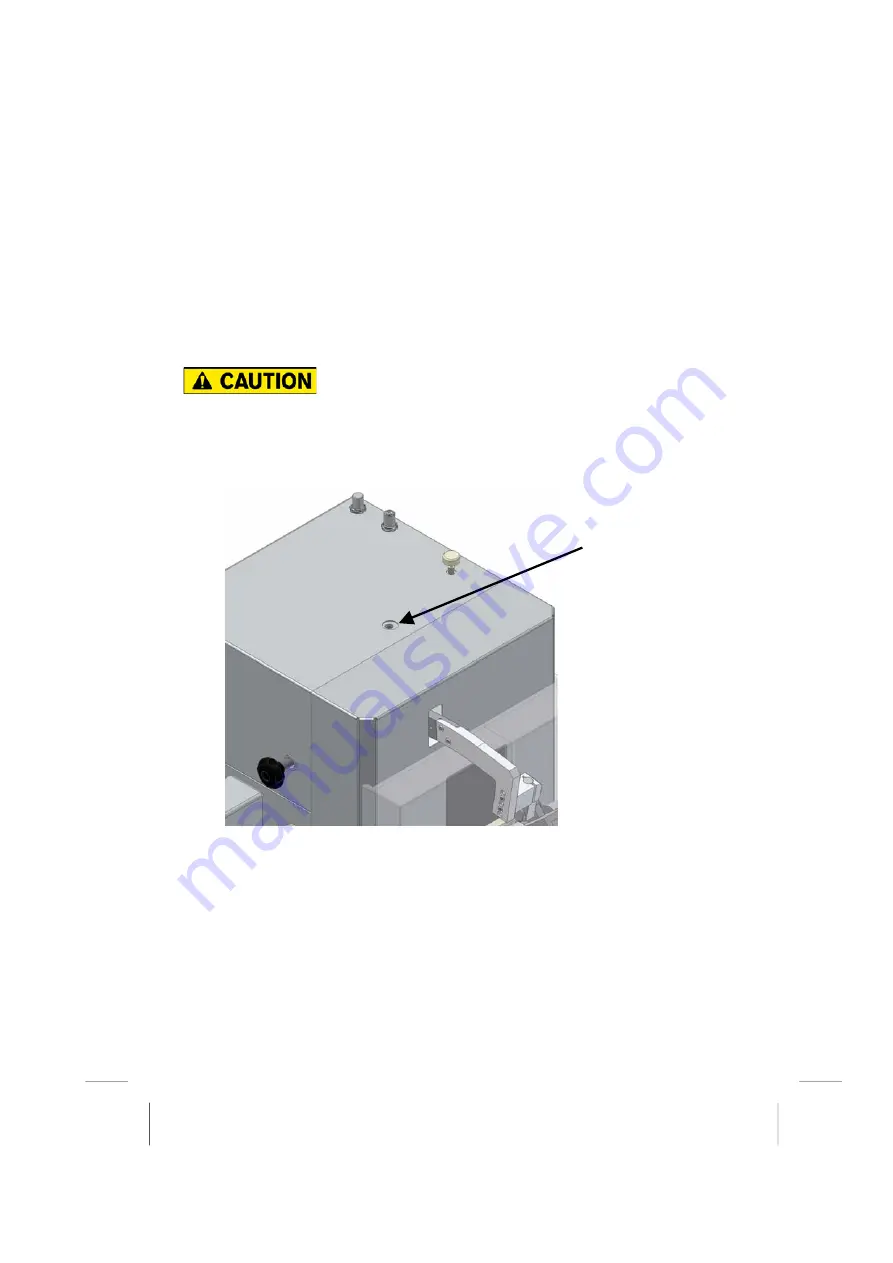
ENSURE THE LIFTING EYE IS SECURELY FIITED
PRIOR TO LIFTING

7)


Using the Lifting eye supplied with the machine and a suitable lifting hoist lift the
machine and place on the work bench as outlined in section 

3.1.1 in the


Operators

Guide. 

The lifting eye is fixed to the top of the machine.

3.1.1


Workbench

It should be of sturdy construction, rigid and free from vibration
It should be sufficiently high to allow the largest operator to sit under comfortably.
Its maximum thickness, at the operator position, should not exceed 60mm.

Its legs or supports should not obstruct the operator.

Lifting eye fits here

Summary of Contents for 4000 Series

Page 1: ...1 Series 4000HS An Operators Guide Version 1 ...

Page 2: ...d in six strategic centres in the USA Asia Europe and the company s customer service support is acknowledged to be the best in the business We trust that you find our product an invaluable tool hope that you will pass on any comments you may have so we can continue to enhance the product and service to you Therefore could you please spend a couple of minutes answering our customer satisfaction que...

Page 3: ...these to DPI Customer Support Dage Precision Industries Rabans Lane Aylesbury Buckinghamshire HP19 8RG ENGLAND Tel 44 1296 317800 Fax 44 1296 435408 Email DPI Support dage group com Microsoft MS DOS Windows Windows95 Windows98 WindowsNT WindowsXP Microsoft Access and Microsoft Excel are registered trademarks of Microsoft Corporation Version 5 Dage Ltd 1998 2003 PRINTED ON CLEAN ROOM FRIENDLY FILM ...

Page 4: ...ing the chair 19 4 2 2 Setting the joysticks 19 4 2 3 Setting the microscope 20 5 UNDERSTANDING THE MACHINE 22 5 1 TURNING ON 22 5 2 TURNING OFF 24 5 3 EMERGENCY STOP BUTTON 25 5 3 1 Procedure For Returning Machine to Operational Use Following an Emergency Stop 25 5 3 2 Removal of other Hazardous energy sources 26 5 4 BASIC OPERATOR CONTROLS 27 5 4 1 On screen controls 27 5 4 2 Keypad controls 28 ...

Page 5: ...removal 56 7 6 2 Shear Test Work holder 56 7 7 HIGH SPEED SHEAR TESTS BALL ALLIGNMENT 57 7 8 ZONE SHEAR TESTING USING THE ZONE SHEAR TABLE 58 7 9 TEST RESULTS 59 7 9 1 List of results 59 7 9 2 Typical XBar Range trend graph 60 7 9 3 Grading the test 61 7 9 4 Number of tests in a sample 62 7 9 5 CPK and other statistics 62 8 CALIBRATION 63 8 1 COLD BUMP PULL CARTRIDGE CALIBRATION 63 8 2 SHEAR CARTR...

Page 6: ...The 4000 is a general purpose machine that can test 100kg die shear and fine pitch wire bonds The 4000HS is designed for high speed applications The 4000HS is capable of testing up to 4M s in shear and 1 3M s in pull The 4000HS Z is a zone shear machine capable of testing in shear up to 80Kg at speeds up to 600mm s and can also be used to perform pull tests up to 1 3M s in the same way as a 4000HS...

Page 7: ...he following Signal Words are used in this guide All safety related notes reminder etc are highlighted in RED colour please read carefully Symbol Meaning DANGER indicates an imminently hazardous situation which if not avoided will result in death or serious injury WARNING indicates a potentially hazardous situation which if not avoided could result in death or serious injury CAUTION indicates a po...

Page 8: ...rk lift truck TIPPING HAZARD Higher than normal Centre of Gravity Do not tip the machine more than 10 as it only has three feet and so will tip easily May cause death or serious injury by crushing CRUSHING HAZARD The Machine is extremely heavy Ensure adequate help is available when positioning the machine as it may be difficult to control any lifting equipment even on a gently sloping floor May ca...

Page 9: ...SURE THE LIFTING EYE IS SECURELY FIITED PRIOR TO LIFTING 7 Using the Lifting eye supplied with the machine and a suitable lifting hoist lift the machine and place on the work bench as outlined in section 3 1 1 in the Operators Guide The lifting eye is fixed to the top of the machine 3 1 1 Workbench It should be of sturdy construction rigid and free from vibration It should be sufficiently high to ...

Page 10: ... REQUIRED TO CONNECT THIS MACHINE TO A POWER SOURCE MUST HAVE AN INTEGRAL EARTH CONNECTION ENSURE THE MAINS SUPPLY TO THE MACHINE IS ADEQUATELY RATED AND FUSED IF IN DOUBT CONSULT A QUALIFIED ELECTRICIAN FOR CONTINUED PROTECTION AGAINST RISK OF FIRE OR DAMAGE TO THE EQUIPMENT REPLACE FUSES ONLY WITH THOSE OF THE SPECIFIED TYPE AND CURRENT RATING IT IS VITAL THAT THE CORRECT VOLTAGE RANGE IS SELECT...

Page 11: ...e It is located on the left hand side of the machine underneath the monitor arm It is essential that the correct voltage is selected and the correct fuse is fitted Plug the mains power lead into the fused connector The AC output can be used to power the PC or monitor Do not power up the machine until all the connections are made There are two circuit breakers on this panel ensure that they are dep...

Page 12: ...ems These connections are on the rear of the machine Computer Link The supplied data lead which plugs into the PC plugs in here Keypad The keypad which is part of the joystick assembly s plugs in here Foot Switch This is where the foot switch plugs in Joystick 1 2 The joystick assembly s plug in here Joystick 1 is normally the right hand joystick and joystick 2 is normally the left hand joystick T...

Page 13: ...ate the vertical lift table which is used during pull tests Compressed nitrogen is a suitable alternative Note The machine will not operate correctly if the supply is contaminated or wet 3 3 2 Setting compressed air regulators There are three regulators located on the top right of the machine which should be set as follows High Speed Bump Pull Rising Table Regulator Secondary Regulator Shear Load ...

Page 14: ...mp may provide it 3 3 4 Services connection There are three service connections on the rear of the machine as shown below Note Any water in the airline is separated and will be discharged from the drain automatically A suitable receptacle must be provided Found in the Right hand bottom corner of the rear of the pneumatic chassis ...

Page 15: ...Any joystick may be fitted to the left or right hand side of the machine handing conversion may be required see the engineers guide A standard configuration would have the joystick with the keypad on the right The fitting procedure is as follows Plug in the electrical connector on the rear of the machine using the left hand right hand labels as a guide Plug in the keypad at the rear of the machine...

Page 16: ...button and the lamp on off switch When the emergency stop button is pressed it will require a reset To reset the switch twist and pull If this is not performed the machine cannot be powered up 4000HS Keyboard Rest Connect the connectors together that supply the emergency stop buttton and the on off switch for the lamp Connect the earth strap Install the keyboard rest using the two screws provided ...

Page 17: ...me of press the 4000HS machine is using a Leica microscope If you experience any difficulties then contact your local Dage representative Supplied with the machine Check mounting pod is orientated as shown Supplementary lens must be fitted ...

Page 18: ...raight and upright 2 Feet flat on the floor or on a suitable footrest 3 Head upright or leaning slightly forward when looking down microscope 4 Elbows below shoulders or slightly forward 5 Fore arms horizontal or slightly raised This drawing shows the features needed to set the ideal operating position Note Attention to these points result in a relaxed sitting position with little or no muscular t...

Page 19: ...e correct seating position as shown 4 2 2 Setting the joysticks The joysticks have been designed for left or right handed use If one configuration does not suit all operators extra joysticks may be needed It will be necessary to reconfigure the joystick axis to move for example the motorised table controls from the left to the right joystick See your engineer Note The standard configuration is des...

Page 20: ... number Angle the microscope to the tool tip and test point in the Y axis Angle the microscope to the tool tip and test point in the X axis Ask your engineer to add your name to the list of operators and re configure the controls if the defaults are not suitable Zoom Control knob Raise and lower microscope as required using the black knob on the left hand side of the machine Angle adjustment centr...

Page 21: ...the machine The microscope is on an arc so the focal length will not change when adjusting the height Set the zoom to the required magnification Note when the zoom is changed the focus and angular alignment may need to be reset Loosen fixing screws Align microscope to test point and tighten fixing screws Height adjustment knob Eyepieces Magnification and focus adjustment ...

Page 22: ...iagnostics and may well report some errors on the hard disk drive This is usually of no consequence but you must choose the FIX option and then the SKIP UNDO option The computer may automatically start the Dage software A screen similar to that shown below will appear Note If this does not appear then you must manually start the Dage software You will usually find an icon labelled Dage Bondtester ...

Page 23: ...e machine is now ready configured as it was last time it was powered off The screen should look similar to that shown below Note If the above screen is a little small on the monitor click the maximise button ...

Page 24: ...hine is being powered up next time Close down the Dage screen by pressing the close button in the top right of the screen Select Start Shutdown from the Windows taskbar at the bottom of the screen Select Shut down the computer and press Yes Wait for the message It s now safe to turn off Your computer Turn off the machine using the switch on the left hand side ...

Page 25: ...r to returning the machine to operational use If a fault condition arises whilst using this machine that is not hazardous then power down the machine in the normal manner Note As part of the preventative maintenance program for these machines it is necessary to inspect and test the guard system with respect to the interlocks and the Emergency Stop button 5 3 1 Procedure For Returning Machine to Op...

Page 26: ...stigate and rectify the cause of this erratic behaviour 5 Check for normal operation 6 Refit cartridge and re check normal operation 7 If all okay then continue using the machine as normal 5 3 2 Removal of other Hazardous energy sources Other hazardous energy sources that are connected to the 4000HS include the air and vacuum supplies Currently the 4000HS has no need for a vacuum supply although t...

Page 27: ...n screen controls The screen shown below is typical of what you may see Note Your line engineer may have given you more access to other controls or removed access to calibration These buttons allow you to choose main functions by using the mouse Secondary buttons allow you to select options within this main function This button allows you to change the language used You can preview the printout of...

Page 28: ...e the last test only Test grade codes 0 9 Not Available Grade Same as T Start Stop a test Open or close the tweezer jaws Same as R Turn on off vacuum supply 1 used to lock the work holder Same as V Balance null the measuring system sometimes needed after replacing a tool Same as Not Available Raise or lower tool for its protection Tool Save feature see section 5 6 Not Available Move to or return f...

Page 29: ...umerical keys can also be used for grading 5 4 4 2 Arrow key jogging The arrow keys may be used to control the x y movement of the table with finer movements more easily than using the joysticks Single presses of an arrow key will move the table a distance set in the Machine Options tab The direction of the arrow points to the next object i e Å key moves the table to the right If the arrow key is ...

Page 30: ...on the right hand side of the machine or other secure shelving The test tools may be left on the cartridge TEST TOOLS ARE SHARP AND SHOULD BE HANDLED WITH CAUTION TEST TOOLS WILL BE DAMAGED IF NOT USED HANDLED OR STORED CORRECTLY The load cells are loaded into the storage shelves from the front of the machine And should always be pushed up to the stops ...

Page 31: ...and drop down on removal Note The guard is not designed to resist excessive force and may itself be damaged by heavy handling When retracted the guard should be firmly against the under side of the cartridge Note If the guard hangs loose it has been damaged and should be serviced by a qualified Dage representative The guard does not lift when storing the cartridge on the side of the machine Option...

Page 32: ...lder without damaging the tool Firstly it can be used to drive the cartridge up by a given distance quickly To set this distance refer to the engineer s manual By default it goes to the top of the axis When the cartridge tool or workholder has been changed press the button again to return to the original position The engineer can also set a time delay After the machine has been unused for this len...

Page 33: ...alise if the guards remain open There is a ten second period where the load cell can be fitted and the guards shut without an error message appearing If more then ten seconds is taken to shut the guards an error message will appear To remove the message and initialise the load cell shut the guards and press retry This screen is shown later in this section THERE MUST BE CLEARANCE TO ENSURE THAT ANY...

Page 34: ...or close the guard doors if they are not already closed and press retry Note If a Zone shear XY table has been fitted to the machine the guards will differ slightly but will function in the same manner as those shown here Note Do not try to fit a cartridge with the guard up This will jam the mechanism Loosen the clamp screw as shown below ...

Page 35: ...itting the load cell in the storage shelves Guide the cartridge with both hands as shown until the two faces indicated touch Use your left thumb to control the speed and force as the connections are made Tighten the clamp screw Once the load cell is fitted and the clamp screw has been tightened close the guard doors Align V slides on the cartridge and machine Clamp screw Upper slide These two face...

Page 36: ...d fingers clear of the underside of the cartridge Loosen the clamp screw Hold the cartridge as shown on the previous section Push it with your left hand thumb until the electrical connection is broken Continue to slide it towards the right until it is clear of the machine Note The guard will lower automatically to protect the tool 6 3 FITTING AND USING WORK HOLDERS Drive the cartridge if fitted up...

Page 37: ...ew located towards the rear of the machine As indicated this stand is also used to hold the calibration weight support for CBP5KgHS load cell only WORK HOLDER AND STAND FOR SHEAR TESTS RATED UP TO 5KG Jaw Tightening Screw Adapter Clamp Screw Adapter Stand Screw Fixing Holes Clamps Front Edge Highest Part of the Work Holder Use this stand to hold the weight support ...

Page 38: ...e work holder and stand are orientated so that the pneumatic air fitting is located towards the rear of the machine Work Holder and Stand For Pull Tests Rated Up To 5Kg Pneumatic air inlet Fixing Holes Slide towards or apart from each other Loosen and tighten as required Up and down motion of rising table Clamps ...

Page 39: ... the section describing this work holder the stand is also fitted to this plate Both the shear work holder and the pull work holder fix to this plate which is part of the XY table assembly picking up on the indicated holes as required The pull stand will only pick up on three of these holes due to the pneumatic air inlet ...

Page 40: ...ts up to 600mm s and high speed single ball shear up to 600mm s using the same work holder The pull work holder can also be fitted to the zone shear table and used as described in the previous sections Package clamping adjustment Work holder Levelling Adjustment Clamp tightening screw Zone Shear Work Holder rated for 80Kg ...

Page 41: ...the 80Kg work holder to the carriage on the y axis of the XY table one in each corner Fitting the 5Kg pull work holder to the zone shear table Three fixing holes Air fitting recess High speed pull testing with a zone shear table is the same as using a high speed table as described in section 6 2 ...

Page 42: ... divided into three areas a Operator name and information b Test Group selection where to save the test results c Other information to be saved with the sample configured by your engineer Note You may be forced to enter new information into these fields 7 1 1 Understanding the screen layout Choose the test group from a list by pressing the arrow This sets up the test Ask which one is appropriate C...

Page 43: ...e fitted with an interlock system This means that if they are open there will be no response from the joysticks or software commands If the doors are opened during a test then the test will stop To remove this error close the guard doors and continue testing NO ATTEMPT SHOULD BE MADE TO OPERATE THE MACHINE WITH THE DOORS OPEN BY OVERRIDING THE INTERLOCKS ...

Page 44: ...ty The cavity should be clear and undamaged These jaws are the same as the jaws used for standard Testing on the 4000 machine Check the alignment of the jaws when closed If the jaws have been bent they must be replaced Clean off any small particles of solder in the cavity by selecting an unwanted ball and manually closing the jaws over it as shown below Larger particles should be dislodged with a ...

Page 45: ...tool guard must be free to operate without hitting the air pipe The tweezers may not operate correctly if rotated more than one quarter of a turn in either direction from this position 7 2 3 Changing tweezer jaws 1 Set the tweezer opening width to maximum by releasing the adjustment screw Do not remove the screw 2 Carefully remove the access screw and it s sealing ring if fitted R Air pipe Rotate ...

Page 46: ...sing a 0 9mm key Note Do not remove the screw 5 Unscrew the tweezer jaws from the body Fitting is the reverse of removal DO NOT OVER TIGHTEN SCREWS Note Bump pull tweezer jaws are precision parts and quite expensive Treat them with care The jaws are specifically designed for the size of the solder ball to be tested Rotate Hold Grub screw ...

Page 47: ...w size is changed or the pressure needs to be reset proceed as follows Turn the pressure control to zero fully anticlockwise Operate the air valve to the jaws by pressing the or button Align the jaws over a ball of the size to be tested Slowly increase the air pressure clockwise until the jaws begin to close Increase the pressure until the jaws have closed around the ball as shown below The jaws s...

Page 48: ...ly using the or button after each adjustment Repeat as required Always take care to align the jaws to the ball 7 2 6 Work Holder Air Pressure Setting Once the jaw clamping pressure and opening width have been set up it is necessary to set up the rising table air pressure using the regulator on the side of the pneumatic chassis Before the test is started the airflow will be off When the test is sta...

Page 49: ... to the bulkhead fitting situated behind the front cover Set the rising table air pressure using the regulator situated on the side of the pneumatic chassis so that during a test the table will rise at the same rate as the load cell The easiest method of setting this up is to do repeat tests to the side of the balls so that physical tests are not performed ...

Page 50: ...50 7 3 BUMP PULL TEST MODES These test modes are set by pressing the Options button Hook mode set to None Jog 1 Test starts 3 Test complete 4 Programmable close time 2 ...

Page 51: ...hen the test has occurred and the load cell has reached the end of its upward travel the cycle will stop allowing the bond site to be inspected and graded For the cycle to continue the user should press the T button or the start icon 2 kg Programmable landing force Jog 1 Programmable close time Jaws close 3 Test starts 4 Programmable hold delay Test complete 5 Auto replace 6 ...

Page 52: ...52 Hook mode set to Auto Programmable close time Jaws close 3 Test starts 4 Test complete 5 Jog 1 2 kg Programmable landing force ...

Page 53: ... auto replace may not always work It is specifically designed for failure mode 2 as described under failure mode below 2 kg Programmable landing force Jog 1 Programmable close time Jaws close 3 Test starts 4 Programmable hold delay Test complete 5 Auto replace 6 ...

Page 54: ...e soldering of the ball to the site failed Mode 2 The bonding of the ball exceeded the tensile strength of the solder Mode 3 The bonding pad failed Mode 4 The bonding of the ball exceeded the tensile strength of the solder or the jaw pressure is too low Ball extrude Mode 4 Ball failure Mode 2 Pad lift Mode 3 Ball lift Mode 1 ...

Page 55: ...r 10Kg at 10mm s In view of this larger shear tools may not be suitable due to excessive loading 7 5 2 Changing a shear tool Note A variety of shear tool sizes are available to best suit the ball clearance procedure If in doubt consult your engineer SHEAR TOOLS ARE SHARP AND SHOULD BE HANDLED WITH CAUTION SHEAR TOOLS WILL BE DAMAGED IF DROPPED DO NOT PRESS HARD ON THE TOOL OR HOLDER 1 Loosen screw...

Page 56: ...IGH SPEED TESTING USING A BS5KGHS 7 6 1 Shear tool quality The tip of the shear tool should be free of chips and damage It should be inspected at regular intervals and replaced if it becomes damaged 7 6 2 Ceramic shear tool removal The ceramic shear tool fitted to the load cell can be removed easily however if it is removed a recalibration will be required 7 6 3 Shear Test Work holder Front of wor...

Page 57: ...escribed in section 6 5 The row of balls to be tested must be up against the front of the shear work holder Once the test is started the sample will move to the front of the machine to allow for acceleration As previously mention this distance varies depending on the test speed set Once this distance has been travelled the sample will then move to the rear of the machine at the set test speed Note...

Page 58: ... on each ball is different and cannot be predicted Because of this force data has limited value and failure mode is used to qualify bond integrity Samples are inspected after shear The percentage of bond failure area Vs solder shear area is used to assess bond strength Individual bonds are often a mixture of some solder shear and some bond failure the percentage of each bond is assessed to the nea...

Page 59: ...n the results screen 7 9 1 List of results Re grade any test by clicking on grade box Add any comments to a test by clicking on comments box and typing Failures did not meet the specified minimum load Look up and down the list using the scroll controls ...

Page 60: ...e trend graph Note many other graphs are available speak to an engineer or your supervisor to establish which you need to use Mean force of each sample Upper and lower control limits are shown in pink Force range of each sample ...

Page 61: ...he small keypad to enter it If you are unsure then you can choose from a list which includes a description by pressing the grade list button To re grade the current test select the required grade on the small keypad or on this list To erase this test press the key on the small keypad To re grade any test click the mouse on the current grade in the results list then select the correct grade To eras...

Page 62: ...expect a fixed number of tests in the sample or it may allow any number In the second case you must use the Save Sample button to let the machine know you are finished You can change erase or re grade an earlier test in the current sample You cannot change any information in the sample once saved 7 9 5 CPK and other statistics Note These statistics apply to the sample being tested ...

Page 63: ...nue to test depending on the machine settings To assist good calibration a number of calibration jigs hooks and weights are available Note It is preferable to wait 10 minutes after fitting a cartridge before calibration BAD CALIBRATION MAY RESULT BY USING INCORRECT PARTS 8 1 COLD BUMP PULL CARTRIDGE CALIBRATION Cold Bump Pull cartridges are calibrated by using Dage designed weights and a special h...

Page 64: ...king the weight as shown below Fit the hook to the Cold Bump Pull cartridge as shown below Tighten the clamp screw Clamp screw This calibration hook should be included with the load cell Remove any jaws which may be fitted to the cartridge ...

Page 65: ...be a gap where indicated Press OK and the machine will automatically lift the weight at least two times the first time is to centralise the weight At the end of the calibration check there is still a gap as shown above If the wire on the weight is bent then it will not be lifted true and the calibration may be incorrect Note The machine automatically detects many of the problems caused by poor wei...

Page 66: ...ed weights and a special jig To calibrate proceed as follows DS80Kg For Use with the Zone Shear Table only DS100KgHS At the time of press the DS100KgHS cartridge is only used for ball clearance This is not intended to be used for zone shear in the current set up In light of this it is not necessary to calibrate this load cell as the data will not be recorded Fit the 80kg calibration jig so that th...

Page 67: ... calibration using the zone shear XY table Fixing Holes Hang the weight which is asked for by the software here Shear tool shear point Front of calibration jig Adapter Plate Fixing Holes One at Each Corner Front of XY Table The adapter plate can only be installed in one orientation ...

Page 68: ...GHS has only one range so only one weight 500g is required for BS5KgHS load cell calibration IT IS VERY IMPORTANT THAT WHEN CALIBRATING A BS5KGHS NOT TO PERFORM A STANDARD SHEAR TEST AS A COLLISION AND DAMAGE IS VERY LIKELY THIS CALIBRATION JIG IS TO BE USED IN CONJUNCTION WITH THE CALIBRATION ROUTINE ONLY Select Calibration as shown below You will need to enter the reference number on the top of ...

Page 69: ...e to the tool tip calibrating the BS5Kg is only performed using a 500g weight To cover the full range of possible forces the results are scaled Place the weight over the pulley 2 1 pulley See section 7 2 Shear Cartridge calibration describing how to fit the weight to the calibration jig ...

Page 70: ... the round pin Press OK and the machine will automatically lift the weight at least two times the first time is to centralise the weight The tool performs the standard land lift shear sequence automatically with pre set parameters Note Excessive bench vibration will cause the calibration to fail Landing surface Round pin ...

Page 71: ...ING A REMOTE MACHINE The second machine will have been connected to the Series 4000 4000HS or 5000 and a test group configured by your engineer to expect test results from it Note The selections made in the New Sample screen are made in the same way as any test It is the test group selected that will instruct the machine to accept data from the second machine Remote machine type shown here ...

Page 72: ...g of readings around the average point To help remove this scattering effect it is usual to compare the average value of a number of tests on the same part a sample A sample would usually be around 5 to 50 similar tests on a single product Your machine may be configured to require a fixed number of tests per sample or may be flexible and allow any number In this case use the Save Sample button to ...

Page 73: ...t these boxes are chosen by your engineer The boxes may be allowed empty or may use the last value or must have a new value every time depending on the engineer s settings Note To avoid typing the same thing every time it is possible to select from a list of the most recent entries by using the arrow in the right of the box 3 You will normally identify yourself to the machine by choosing your name...

Page 74: ...cold bump pull calibration after the weight is lowered for the first time the hook must not be touching the wire or the weight as this is when a zero weight reading is taken for reference If the wire on the weight is bent the weight may lift at an angle This may lead to an incorrect reading so carefully straighten the wire and try again After the first lift and lower there could be from one to ten...

Page 75: ...he key on the keypad Once pressed set the tool position to the height required and release c Sometimes the tool will be in collision with an object and will not move away Move the joystick in the direction required to free the tool and release Press the button on the screen Repeat the last two instructions until the tool moves free 10 3 2 The table will not drive or moves in one direction only Thi...

Reviews: