


- 64 -
Service manual WP 895/895F, CP885/885F
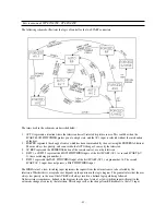
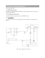
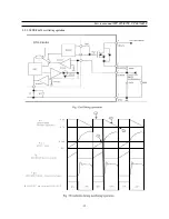
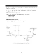
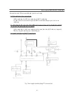
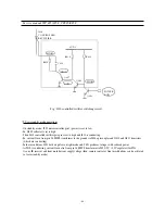
* power supply functioning during TV set normal run mode
- I801 transmits controlled pulses to T801 which generates DC voltages after rectifications by secondary part diodes
and electro capacitors (by example by D820 and C813 on 143V supply voltage line).
- 8V, 5V, 3.3V supply voltage lines have stabilized voltages obtained by I820, I822, I823 voltage regulators.
- On 143V supply voltage line, R823 resistor has been chosen to reach exact DC voltage required on this line.
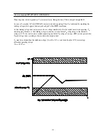
- 143V supply voltage line includes an IC error amplifier (I806) which corrects unexpected DC voltage variations on
this line.
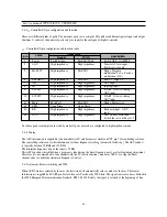
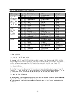
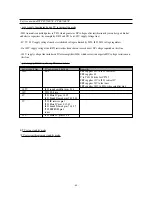
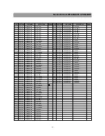
* power supply IC delivery during TV set normal run
power supply line
IC power supply delivery
Remarks
143V
FBT
FBT supplies 43V to I301 vertical IC
FBT supplies 43
V to T401 H- drive for CP785
FBT supplies 12V to I301 vertical IC
FBT supplies 33V to the tuner
FBT supplies 188V to I901 video amplifier pin 6
14.5V
I602 sound amplifier pins 3-16
14V
T401 H- drive
8V
I501 Main IC pins 14-39
I601 Sound Demod pins 38-39-40
5V
I703 IR receiver pin 1
I501 Main IC pins 3-15-45
I601 Sound Demod pins 7-18-57
I702 EEPROM pin 8
tuner
3.3V
I501 Main IC pins 25-54
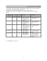
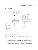
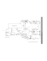
b) TV set on stand-by mode
* TV set circuit diagram on stand-by mode
Summary of Contents for CP-885
Page 32: ... 31 Service manual WP 895 895F CP885 885F Block diagram TDA8944J ...
Page 35: ... 34 Service manual WP 895 895F CP885 885F ...
Page 37: ... 36 Service manual WP 895 895F CP885 885F Block diagram TDA6107Q ...
Page 42: ... 41 Service manual WP 895 895F CP885 885F 5 Circuit description 5 1 Block diagram ...
Page 60: ... 59 Service manual WP 895 895F CP885 885F 5 9 2 2 STR F6654 oscillating operation ...
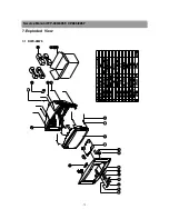
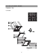
Page 76: ...Service Manual WP 895 895F CP885 885F 75 7 Exploded View 7 1 DWX 28W5 ...
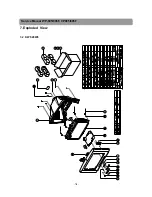
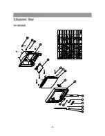
Page 77: ...Service Manual WP 895 895F CP885 885F 76 7 Exploded View 7 2 DWF 28W8 ...
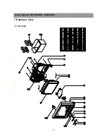
Page 78: ...Service Manual WP 895 895F CP885 885F 77 7 Exploded View 7 3 DTF 29U8 ...
Page 79: ...Service Manual WP 895 895F CP885 885F 78 7 Exploded View 7 4 DTP 28A7 ...
Page 80: ...Service Man ual WP 895 895F CP885 885F 79 7 Exploded View 7 5 DTP 28B1 ...
Page 81: ...Service Man ual WP 895 895F CP885 885F 80 7 Exploded View 7 6 DTP 28G7 ...
Page 82: ...Service Manual WP 895 895F CP885 885F 81 7 Exploded View 7 7 DTP 28G8 ...
Page 83: ...PRINTED CIRCUIT BOARD PCB MAIN ...
Page 84: ......
Page 85: ......


