Fo
- 3 -
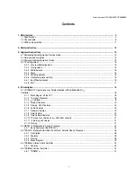
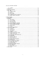
5-4-1 Introduction........................................................................................................................................... 49
5-4-2 CPU ...................................................................................................................................................... 49
............................................................................... 50
5-4-4 Tuning .................................................................................................................................................. 50
5-4-5 Automatic
rmat switching and WSS ............................................................................................... 50
5-4-6 EXTERNAL source control logic
........................................................................................................... 51
5-4-7 Over Current Protection
........................................................................................................................ 53
5-5Teletext Display ................................................................................................................................................. 53
5-6 Sound processing
............................................................................................................................................... 54
5-6-1 Analogue sound IF-input section
............................................................................................................ 54
5-6-2 Quadrature Mixers ................................................................................................................................ 54
5-6-3 Phase and AM discr imination........................................................................................................... 54
5-6-4 NICAM decoder.................................................................................................................................... 55
5-6-5 DSP section.......................................................................................................................................... 55
5-6-6 Sound Mode switching.......................................................................................................................... 55
5-7 Sound amplification........................................................................................................................................... 55
5-7-1 Power amplifier..................................................................................................................................... 55
5-7-2 Mode selection....................................................................................................................................... 56
5-8 Vertical deflection............................................................................................................................................. 56
5-8-1 Flyback voltage..................................................................................................................................... 56
5-8-2 Protection.............................................................................................................................................. 56
5-8-3 Guard circuit.......................................................................................................................................... 56
5-8-4 Damping resistor................................................................................................................................... 56
5-8-5 EAST-WEST Amplifier (TDA8358J only)............................................................................................... 56
5-9 Power supply (STR F6653)
.. .............................................................................................................................. 57
5-9-1 STR-F6654 gener
aral description......................................................................................................... 57
5-9-2 Power supply primary par t operations
................................................................................................... 57
5-10TV start-up, TV normal run and stand by mode operations
............................................................................... 61
5-10-1 TV start-up operations .......................................................................................................................... 61
5-10-2 TV normal run and stand-by mode operations
....................................................................................... 62
6 - Service pa
rt
s list
..
................................................................................................................................................. 67
7 - Exploded
View ........................................................................................................................................................ 75
8 - PCB Layout
9 - Circuit Diagram
Service manual WP-895/895F. CP885/885F
5-4-3
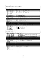
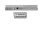
-Controller I/O pin configuration and function
7-1 DWX-28W5
7-2 DWF-28W8
7-3 D T F-29U8
7-4 D T P-28A7
7-5 D T P-28B1
7-6 D T P-28G7
7-7 D T P-28G8
.......................................................................................................................................................
.......................................................................................................................................................
.......................................................................................................................................................
.......................................................................................................................................................
.......................................................................................................................................................
.......................................................................................................................................................
.......................................................................................................................................................
75
76
77
78
79
80
81
Summary of Contents for CP-885
Page 32: ... 31 Service manual WP 895 895F CP885 885F Block diagram TDA8944J ...
Page 35: ... 34 Service manual WP 895 895F CP885 885F ...
Page 37: ... 36 Service manual WP 895 895F CP885 885F Block diagram TDA6107Q ...
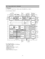
Page 42: ... 41 Service manual WP 895 895F CP885 885F 5 Circuit description 5 1 Block diagram ...
Page 60: ... 59 Service manual WP 895 895F CP885 885F 5 9 2 2 STR F6654 oscillating operation ...
Page 76: ...Service Manual WP 895 895F CP885 885F 75 7 Exploded View 7 1 DWX 28W5 ...
Page 77: ...Service Manual WP 895 895F CP885 885F 76 7 Exploded View 7 2 DWF 28W8 ...
Page 78: ...Service Manual WP 895 895F CP885 885F 77 7 Exploded View 7 3 DTF 29U8 ...
Page 79: ...Service Manual WP 895 895F CP885 885F 78 7 Exploded View 7 4 DTP 28A7 ...
Page 80: ...Service Man ual WP 895 895F CP885 885F 79 7 Exploded View 7 5 DTP 28B1 ...
Page 81: ...Service Man ual WP 895 895F CP885 885F 80 7 Exploded View 7 6 DTP 28G7 ...
Page 82: ...Service Manual WP 895 895F CP885 885F 81 7 Exploded View 7 7 DTP 28G8 ...
Page 83: ...PRINTED CIRCUIT BOARD PCB MAIN ...
Page 84: ......
Page 85: ......


