


- 61 -
Service manual WP 895/895F, CP885/885F
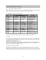
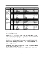
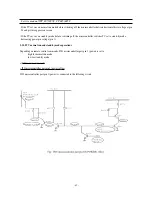
5-10 TV start-up, TV normal run and stand by mode operations
5-10-1 TV start-up operations
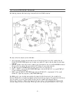
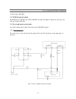
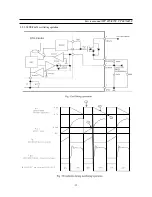
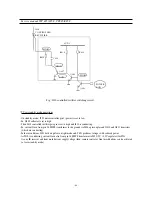
* Schematic diagram for start-up operations
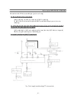
* TV start-up and microcontroller initialisation
- When SW801 power switch is pushed, main AC voltage is applied to T801 transformer (after rectification by D801...
D804 diodes). Then, T801 SMPS transformer starts operating and supplies DC voltage to I823 (5V regulator).
- This regulator provides 5V / 3.3V DC voltage to I501 microcontroller power supply pins (pin 3 / pin 54) and to the
reset pulse circuit which provides reset pulse to I501 microcontroller reset pin (pin 58).
- Then, the microcontroller starts its initialisation. Its power pin (pin 1) is set to high which allows delivery of power
supply voltages (123V, 8V, 5V...). At this step, all IC’s start working but no picture appears on screen: I501 IC
doesn’t provide horizontal drive voltage.
- Then, the microcontroller consults I702 EEPROM via I2C bus to know the last TV set mode (normal run mode or
stand-by mode ) before switching off.
Summary of Contents for CP-885
Page 32: ... 31 Service manual WP 895 895F CP885 885F Block diagram TDA8944J ...
Page 35: ... 34 Service manual WP 895 895F CP885 885F ...
Page 37: ... 36 Service manual WP 895 895F CP885 885F Block diagram TDA6107Q ...
Page 42: ... 41 Service manual WP 895 895F CP885 885F 5 Circuit description 5 1 Block diagram ...
Page 60: ... 59 Service manual WP 895 895F CP885 885F 5 9 2 2 STR F6654 oscillating operation ...
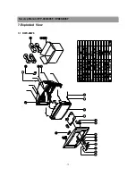
Page 76: ...Service Manual WP 895 895F CP885 885F 75 7 Exploded View 7 1 DWX 28W5 ...
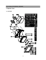
Page 77: ...Service Manual WP 895 895F CP885 885F 76 7 Exploded View 7 2 DWF 28W8 ...
Page 78: ...Service Manual WP 895 895F CP885 885F 77 7 Exploded View 7 3 DTF 29U8 ...
Page 79: ...Service Manual WP 895 895F CP885 885F 78 7 Exploded View 7 4 DTP 28A7 ...
Page 80: ...Service Man ual WP 895 895F CP885 885F 79 7 Exploded View 7 5 DTP 28B1 ...
Page 81: ...Service Man ual WP 895 895F CP885 885F 80 7 Exploded View 7 6 DTP 28G7 ...
Page 82: ...Service Manual WP 895 895F CP885 885F 81 7 Exploded View 7 7 DTP 28G8 ...
Page 83: ...PRINTED CIRCUIT BOARD PCB MAIN ...
Page 84: ......
Page 85: ......