- 46 -
Service manual WP 895/895F, CP885/885F
5-3-8 Adaptive Comb Filter (VCT3834A only)
The adaptive comb filter is used for high-quality luminance/chrominance separation for PAL or NTSC signals. The
comb filter improves the luminance resolution (bandwidth) and reduces interferences like cross-luminance and
cross-color artefacts. The adaptive algorithm can eliminate most of the mentioned errors without introducing new
artefacts or noise. The filter uses two line delays to process the information of three adjacent video lines. To have a
fixed phase relationship of the colour subcarrier in the three channels, the system clock (20.25 MHz) is fractionally
locked to the colour subcarrier. This allows the processing of all colour standards and substandards using a single
crystal frequency. The CVBS signal in the three channels is filtered at the subcarrier frequency by a set of bandpass/
notch filters. The output of the three channels is used by the adaptation logic to select the weighting that is used to
reconstruct the luminance/chrominance signal from the 4 bandpass/notch filter signals. By using soft mixing of the 4
signals switching artefacts of the adaption algorithm are completely suppressed. The comb filter uses the middle line as
reference, therefore, the comb filter delay is one line. If the comb filter is switched off, the delay lines are used to pass
the luma/ chroma signals from the A/D converters to the luma/ chroma outputs. Thus, the comb filter delay is always
one line.
5-3-9 Color Decoder
In this block, the standard luma/chroma separation and multi-standard colour demodulation is carried out. The colour
demodulation uses an asynchronous clock, thus allowing a unified architecture for all colour standards.
The colour killer uses the burst-phase/ burst-frequency measurement to identify a PAL/NTSC or SECAM colour signal.
For PAL/NTSC, the colour is switched off (killed) as long as the colour subcarrier PLL is not locked. For SECAM, the
killer is controlled by the toggle of the burst frequency. The burst amplitude measurement is used to switch-off the
colour if the burst amplitude is below a programmable threshold. Thus, colour will be killed for very noisy signals.
The colour amplitude killer has a programmable hysteresis.
The burst-frequency measurement is also used for automatic standard recognition (together with the status of horizontal
and vertical locking) thus allowing a completely independent search of the line and colour standard of the input signal.
The following standards can be distinguished:
PAL B,G,H,I; NTSC M; SECAM; NTSC 44; PAL M; PAL N; PAL 60. In AV mode or when Prg No 0 is selected all the
standards above are enabled by the controlling software. In INSTALL menu the controlling software enables PAL B,G,
H,I and SECAM detection. The colour standard for each program number is stored in EEPROM. Outside INSTALL
menu and for programmes numbers 1 to 99, the auto colour detection is disabled, the colour standard is recall from
EEPROM and forced.
5-3-10 Horizontal Scaler (VCT3834A only)
The 4:2:2 YC r C b signal from the colour decoder is processed by the horizontal scaler. The scaler block allows a
linear or nonlinear horizontal scaling of the input video signal in the range of 0.25 to 4. Nonlinear scaling, also called
“Panoramavision”, provides a geometrical distortion of the input picture. It is used to fit a picture with 4:3 format on a
16:9 screen by stretching the picture geometry at the borders. Also, the inverse effect can be produced by the scaler.
The scaler contains a programmable decimation filter, a 1-line FIFO memory, and a programmable interpolation filter.
Summary of Contents for CP-885
Page 32: ... 31 Service manual WP 895 895F CP885 885F Block diagram TDA8944J ...
Page 35: ... 34 Service manual WP 895 895F CP885 885F ...
Page 37: ... 36 Service manual WP 895 895F CP885 885F Block diagram TDA6107Q ...
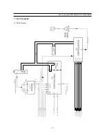
Page 42: ... 41 Service manual WP 895 895F CP885 885F 5 Circuit description 5 1 Block diagram ...
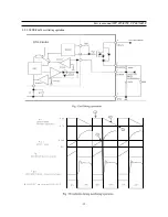
Page 60: ... 59 Service manual WP 895 895F CP885 885F 5 9 2 2 STR F6654 oscillating operation ...
Page 76: ...Service Manual WP 895 895F CP885 885F 75 7 Exploded View 7 1 DWX 28W5 ...
Page 77: ...Service Manual WP 895 895F CP885 885F 76 7 Exploded View 7 2 DWF 28W8 ...
Page 78: ...Service Manual WP 895 895F CP885 885F 77 7 Exploded View 7 3 DTF 29U8 ...
Page 79: ...Service Manual WP 895 895F CP885 885F 78 7 Exploded View 7 4 DTP 28A7 ...
Page 80: ...Service Man ual WP 895 895F CP885 885F 79 7 Exploded View 7 5 DTP 28B1 ...
Page 81: ...Service Man ual WP 895 895F CP885 885F 80 7 Exploded View 7 6 DTP 28G7 ...
Page 82: ...Service Manual WP 895 895F CP885 885F 81 7 Exploded View 7 7 DTP 28G8 ...
Page 83: ...PRINTED CIRCUIT BOARD PCB MAIN ...
Page 84: ......
Page 85: ......

