xStack Storage Management Center Software User’s Guide
13
2.3.3 View Panel
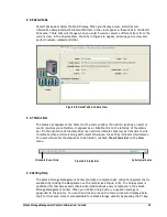
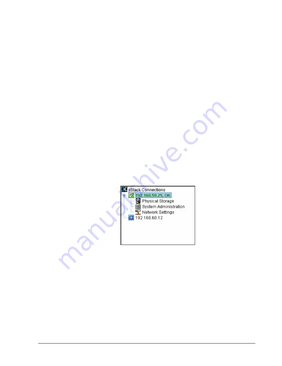
The View panel appears below the toolbar. The View panel shows the IP address of each
xStack Storage that has been added to the Management Center (an xStack Storage must be
added to the console in order to be managed by it). In Figure 2-5, two xStack Storage
systems have been added to the Management Center, one with an IP address of
192.168.59.25 and another with the IP address 192.168.60.12.
While you can add many xStack Storage systems to the Management Center, the console lets
you access one xStack Storage at a time. To identify the xStack Storage that is currently
being managed, the IP address of the currently managed system appears in a box along with
color-coded icons that indicates its operating status. In the View panel in Figure 2-5, the
xStack Storage corresponding to IP address 192.168.59.25 is being managed. The checkmark
and OK next to this IP address, and the green color coding of the IP address itself, indicate
that this xStack Storage is operating normally.
When the IP address of the currently managed xStack Storage is highlighted, the Volume
View is displayed. Below the IP address of the currently managed xStack Storage are links
you can click to display the other console views for that array. In Figure 2-5, clicking
Physical Storage displays the Physical Storage View of the xStack Storage corresponding to
IP address 192.168.59.25.
If you add an xStack Storage system to the Management Center (described in section 8.1),
you can log in to that system by clicking its IP address in the View pane. In Figure 2-5,
clicking the IP address 192.168.60.12 will display the login page for the xStack Storage
associated with that IP address.
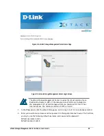
Figure 2-5. View panel
Summary of Contents for DSN-5210-10 - xStack Storage Area Network Array Hard Drive
Page 9: ...xStack Storage Management Center Software User s Guide ix This Page Left Intentionally Blank ...
Page 10: ......
Page 90: ...80 Chapter 5 Managing Physical Storage This Page Left Intentionally Blank ...
Page 110: ...100 Chapter 6 System Administration Figure 6 18 Advanced Settings Tab ...
Page 132: ...122 Chapter 8 Performing System Actions THIS PAGE LEFT INTENTIONALLY BLANK ...
Page 136: ...126 Chapter 9 Best Practices This Page Left Intentionally Blank ...
Page 144: ...134 Appendix A Menu Summary THIS PAGE LEFT INTENTIONALLY BLANK ...
Page 148: ...138 Appendix B Factory Default Settings THIS PAGE LEFT INTENTIONALLY BLANK ...


