DES-1228/ME Metro Ethernet Managed Switch Hardware Installation Guide
Chapter 5 – Web-based Switch Configuration
Page | 27
W
EB
-
BASED
U
SER
I
NTERFACE
The user interface provides access to various Switch configuration and management windows, allows you to view
performance statistics, and permits you to graphically monitor the system status.
A
REAS OF THE
U
SER
I
NTERFACE
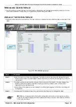
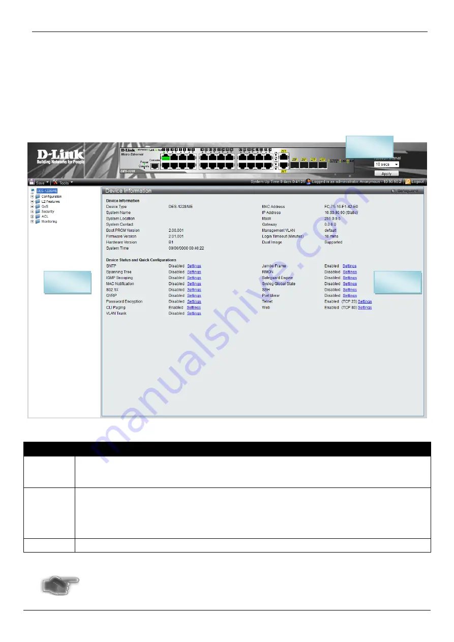
The figure below shows the user interface. The user interface is divided into three distinct areas as described in the
table.
Figure 5- 2. Main Web-Manager page
Area
Function
Area 1:
Select the folder or window to be displayed. The folder icons can be opened to display the hyper-
linked window buttons and subfolders contained within them. Click the D-Link logo to go to the D-
Link website.
Area 2:
Presents a graphical near real-time image of the front panel of the Switch. This area displays the
Switch's ports and expansion modules, showing port activity, duplex mode, or flow control,
depending on the specified mode.
Various areas of the graphic can be selected for performing management functions, including port
configuration.
Area 3:
Presents switch information based on your selection and the entry of configuration data.
NOTICE:
Any changes made to the Switch configuration during the current session must be
saved in the Save Changes web menu (explained below) or use the command line interface
(CLI) command save.
Area 3
Area 1
Area 2

