background image

DES-1228/ME Metro Ethernet Managed Switch Hardware Installation Guide 

Chapter 2 - Installation 

Page | 15 


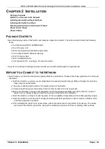
I

NSTALLING THE 

S

WITCH WITHOUT THE 

R

ACK


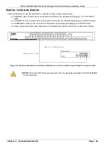
When installing the Switch on a desktop or shelf, the rubber feet included with the Switch should first be attached. 

Attach these cushioning feet on the bottom at each corner of the device. Allow enough ventilation space between 
the Switch and any other objects in the vicinity. 


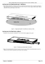
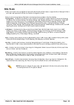
Figure 2 - 1. Preparing the switch for installation on a desktop or shelf 


I

NSTALLING THE 

S

WITCH IN A 

R

ACK


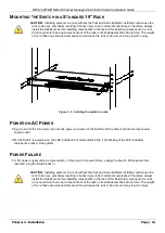
The Switch can be mounted in a standard 19" rack. Use the following diagrams as a guide. 


Figure 2 - 2. Fastening mounting brackets to the switch 


Fasten the mounting brackets to the Switch using the screws provided. With the brackets attached securely, the 

Switch can be mounted in a standard rack as shown in the next figure. 

Summary of Contents for DES-1228/ME

Page 1: ...DES 1228 ME Metro Ethernet Managed Switch Hardware Installation Guide Page 1 ...

Page 2: ...nterference in which case the user will be required to correct the interference at his own expense CE Mark Warning This is a Class A product In a domestic environment this product may cause radio interference in which case the user may be required to take adequate measures Warnung Dies ist ein Produkt der Klasse A Im Wohnbereich kann dieses Produkt Funkstoerungen verursachen In diesem Fall kann vo...

Page 3: ...ng the Switch in a Rack 15 Mounting the Switch in a Standard 19 Rack 16 Power on AC Power 16 Power Failure 16 Chapter 3 Connecting the Switch 17 Switch to End Node 17 Switch to Hub or Switch 18 Chapter 4 Introduction to Switch Management 19 Management Options 19 Web based Management Interface 19 SNMP Based Management 19 Connecting the Console Port 19 First Time Connecting to the Switch 20 Password...

Page 4: ... prompts appearing on your screen For example You have mail Bold font is also used to represent filenames program names and commands For example use the copy command Boldface Typewriter Font Indicates commands and responses to prompts that must be typed exactly as printed in the manual Initial capital letter Indicates a window name Names of keys on the keyboard have initial capitals For example Cl...

Page 5: ...pe of external power source indicated on the electrical ratings label If you are not sure of the type of power source required consult your service provider or local power company To help avoid damaging your system be sure the voltage on the power supply is set to match the power available at your location o 115 volts V 60 hertz Hz in most of North and South America and some Far Eastern countries ...

Page 6: ... load the heaviest item in the rack first Make sure that the rack is level and stable before extending a component from the rack Use caution when pressing the component rail release latches and sliding a component into or out of a rack the slide rails can pinch your fingers After a component is inserted into the rack carefully extend the rail into a locking position and then slide the component in...

Page 7: ...n also take the following steps to prevent damage from electrostatic discharge ESD 1 When unpacking a static sensitive component from its shipping carton do not remove the component from the antistatic packing material until you are ready to install the component in your system Just before unwrapping the antistatic packaging be sure to discharge static electricity from your body 2 When transportin...

Page 8: ...ers switches and other networking devices The dual speed ports use standard twisted pair cabling and are ideal for segmenting networks into small connected sub networks for superior performance Each 10 100 port can support up to 200 Mbps of throughput in full duplex mode In addition the Switch has two 100 1000 SFP and two 10 100 1000BASE T SFP Combo ports These gigabit combo ports are ideal for co...

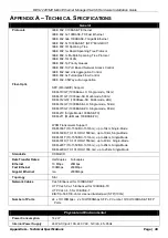
Page 9: ...uto MDI X MDI II cross over supported except for speed 1000M force mode SFP Combo IEEE 802 3 compliant IEEE 802 3u compliant IEEE 802 3ab compliant IEEE 802 3x flow control support in full duplex SFP Transceivers Supported DEM 310GT 1000Base LX Single mode 10km DEM 311GT 1000ase SX Mutli mode 500m DEM 312GT2 1000Base SX Multi mode 2km DEM 314GT 1000BASE LH Single mode 50km DEM 315GT 1000BASE ZX Si...

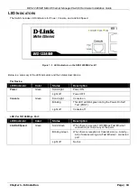
Page 10: ...or Color Status Description Power Green Solid Light Power ON Light off Power OFF Console Green Solid Light Console on Blinking This LED will blink green during the Power On Self Test POST Light off Console off LED Per 10 100 Mbps Port LED Indicator Color Status Description Link Act Speed Green Solid Green When there is a secure 10 100Mbps Fast Ethernet connection or link at any of the ports Blinki...

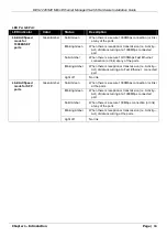
Page 11: ...0 100Mbps Fast Ethernet connection or link at any of the ports Blinking Amber When there is reception or transmission i e Activity Act of data occurring at a Fast Ethernet connected port Light off No link Link Act Speed mode for SFP ports Green Amber Solid Green When there is a secure 1000Mbps connection or link at the ports Blinking Green When there is reception or transmission i e Activity Act o...

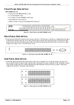
Page 12: ...lug in the female connector of the provided power cord into this socket and the male side of the cord into a power outlet The Switch automatically adjusts its power setting to any supply voltage in the range of 100 240 VAC at 50 60 Hz Figure 1 3 Rear panel view of the DES 1228 ME Ver B1 SIDE PANEL DESCRIPTION The left and right hand panels of the Switch have heat vents to dissipate heat Do not blo...

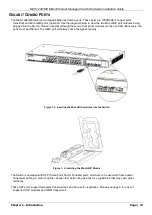
Page 13: ...l modules can be used simultaneously the ports must be different The GBIC port will always have the highest priority Figure 1 5 Inserting the Mini GBIC modules into the Switch Figure 1 6 Installing the Mini GBIC Module The Switch is equipped with SFP Small Form Factor Portable ports which are to be used with fiber optical transceiver cabling in order to uplink various other networking devices for ...

Page 14: ...he Switch may greatly affect its performance Please follow these guidelines for setting up the Switch Install the Switch on a sturdy level surface that can support at least 4 24kg 9 35lbs of weight Do not place heavy objects on the Switch The power outlet should be within 1 82 meters 6 feet of the Switch Visually inspect the power cord and see that it is fully secured to the AC power port Make sur...

Page 15: ...the device Allow enough ventilation space between the Switch and any other objects in the vicinity Figure 2 1 Preparing the switch for installation on a desktop or shelf INSTALLING THE SWITCH IN A RACK The Switch can be mounted in a standard 19 rack Use the following diagrams as a guide Figure 2 2 Fastening mounting brackets to the switch Fasten the mounting brackets to the Switch using the screws...

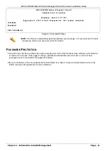
Page 16: ...e end of the AC power cord into the power connector of the Switch and the other end into the local power source outlet After the Switch is powered on the LED indicators will momentarily blink This blinking of the LED indicators represents a reset of the system POWER FAILURE For AC power supply units as a precaution in the event of a power failure unplug the Switch When power has resumed plug the S...

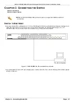
Page 17: ...NODE End nodes include PCs outfitted with a 10 100 or 1000 Mbps RJ 45 Ethernet Fast Ethernet Network Interface Card NIC and most routers An end node can be connected to the Switch via a twisted pair Category 3 4 or 5 UTP STP cable The end node should be connected to any of the ports of the Switch Figure 3 1 DES 1228 ME Ver B1 connected to an end node The Link Act LEDs for each UTP port will light ...

Page 18: ...100BASE TX hub or switch can be connected to the Switch via a twisted pair Category 5 UTP STP cable A 1000BASE T switch can be connected to the Switch via a twisted pair Category 5e UTP STP cable A switch supporting a fiber optic uplink can be connected to the Switch s SFP ports via fiber optic cabling Figure 3 2 Switch connected to a normal non Uplink port on a hub or switch using a straight or c...

Page 19: ...B objects to generate statistics and counters CONNECTING THE CONSOLE PORT The Switch includes an RJ 45 serial port that enables a connection to a computer or terminal for monitoring and configuring the Switch This port is a female DB 9 connector implemented as a data terminal equipment DTE connection To use the console port you need the following equipment A terminal or a computer with both a seri...

Page 20: ...ons If you still do not see anything try rebooting the Switch by disconnecting its power supply Once connected to the console the screen below will appear on your console screen This is where the user will enter commands to perform all the available management functions The Switch will prompt the user to enter a user name and a password Upon the initial connection there is no user name or password...

Page 21: ...nistrator level privileges It is recommended to create at least one Admin level user account for the Switch PASSWORD PROTECTION The Switch does not have a default user name and password One of the first tasks when settings up the Switch is to create user accounts Once logged in using a predefined administrator level user name users will have privileged access to the Switch s management software Af...

Page 22: ...uption please refer to the section titled Password Recovery Procedure in Appendix B of the CLI Reference Guide which will guide you through the steps necessary to resolve this issue SNMP SETTINGS Simple Network Management Protocol SNMP is an OSI Layer 7 Application Layer designed specifically for managing and monitoring network devices SNMP enables network management stations to read and modify th...

Page 23: ...essages may be encrypted To read more about how to configure SNMP v 3 settings for the Switch read the section entitled Management TRAPS Traps are messages that alert network personnel of events that occur on the Switch The events can be as serious as a reboot someone accidentally turned OFF the Switch or less serious like a port status change The Switch generates traps and sends them to the trap ...

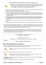
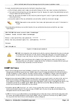
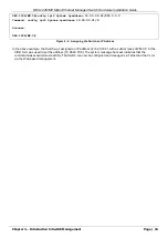
Page 24: ...ation window in the Configuration folder The IP address for the Switch must be set before it can be managed with the Web based manager The Switch IP address can be automatically set using BOOTP or DHCP protocols in which case the actual address assigned to the Switch must be known The IP address may be set using the Command Line Interface CLI over the console serial port as follows Starting at the...

Page 25: ... 10 90 90 91 8 Success DES 1228 ME 5 Figure 4 5 Assigning the Switch an IP Address In the above example the Switch was assigned an IP address of 10 90 90 91 with a subnet mask of 255 0 0 0 the CIDR form was used to set the address 10 90 90 91 8 The system message Success indicates that the command was executed successfully The Switch can now be configured and managed via Telnet and the CLI or via ...

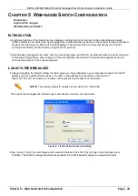
Page 26: ... are different ways to access the same internal switching software and configure it Thus all settings encountered in web based management are the same as those found in the console program LOGIN TO WEB MANAGER To begin managing the Switch simply run the browser you have installed on your computer and point it to the IP address you have defined for the device The URL in the address bar should be in...

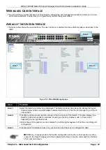
Page 27: ...der icons can be opened to display the hyper linked window buttons and subfolders contained within them Click the D Link logo to go to the D Link website Area 2 Presents a graphical near real time image of the front panel of the Switch This area displays the Switch s ports and expansion modules showing port activity duplex mode or flow control depending on the specified mode Various areas of the g...

Page 28: ...o Assign Settings Port Trunking LACP Port Settings Traffic Segmentation L2PT Settings BPDU Protection Settings IGMP Snooping Port Mirror Loopback Detection Settings Spanning Tree Forwarding Filtering and LLDP QoS Contains main windows concerning Bandwidth Control Traffic Control 802 1p Default Priority 802 1p User Priority QoS Scheduling Settings Priority Mapping TOS Mapping and DSCP Mapping Secur...

Page 29: ... 1000BASE LH Single mode 50km DEM 315GT 1000BASE ZX Single mode 80km DEM 210 Single Mode 100BASE FX DEM 211 Multi Mode 100BASE FX WDM Transceivers Support DEM 330T TX 1550 RX 1310nm up to 10km Single Mode DEM 330R TX 1310 RX 1550nm up to 10km Single Mode DEM 331T TX 1550 RX 1310nm up to 40km Single Mode DEM 331R TX 1310 RX 1550nm up to 40km Single Mode DEM 220T TX 1550 RX 1310nm up to 20km Single ...

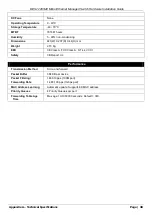
Page 30: ...nsions 441 W X 207 D X 44 H mm Weight 2 15 Kg EMI CE Class A FCC Class A C Tick VCCI Safety CB Report UL Performance Transmission Method Store and forward Packet Buffer 384 KB per device Packet Filtering Forwarding Rate 148 810 pps 100M port 1 488 100 pps 1Gbps port MAC Address Learning Automatic update Supports 8K MAC address Priority Queues 4 Priority Queues per port Forwarding Table Age Time Ma...

Page 31: ... these products for matching cable pin assignment The following diagrams and tables show the standard RJ 45 receptacle connector and their pin assignments Figure B 1 The standard RJ 45 port and connector RJ 45 Pin Assignments Contact MDI X Port MDI II Port 1 RD receive TD transmit 2 RD receive TD transmit 3 TD transmit RD receive 4 1000BASE T 1000BASE T 5 1000BASE T 1000BASE T 6 TD transmit RD rec...

Page 32: ...he standard Console to DJ 45 receptacle connector and their pin assignments Figure B 2 Console to RJ 45 Cable Console RJ 45 Pin Assignments Pin Console DB9 RS232 RJ 45 1 Not Used Not Used 2 RXD Not Used 3 TXD TXD 4 Not Used GND 5 GND shared GND 6 Not Used RXD 7 Not Used Not Used 8 Not Used Not Used 6 0 0HWUR WKHUQHW 0DQDJHG 6ZLWFK DUGZDUH QVWDOODWLRQ XLGH ...

Page 33: ...00ase SX Multi mode 500m DEM 312GT2 1000Base SX Multi mode 2km DEM 314GT 1000BASE LH Single mode 50km DEM 315GT 1000BASE ZX Single mode 80km DEM 210 100BASE FX Single mode 15km DEM 211 100BASE FX Multi mode 2km DEM 220T 100BASE BX Single mode Up to 20km DEM 220R 100BASE BX Single mode Up to 20km DEM 330T TX 1550 RX 1310nm Single mode Up to 10km DEM 330R TX 1310 RX 1550 nm Single mode Up to 10km DE...

Page 34: ...iquidators expressly disclaim their warranty obligation pertaining to the product and in that case the product is being sold As Is without any warranty whatsoever including without limitation the Limited Warranty as described herein notwithstanding anything stated herein to the contrary Submitting A Claim The customer shall return the product to the original purchase point based on its return poli...

Page 35: ...opyright Statement No part of this publication or documentation accompanying this product may be reproduced in any form or by any means or used to make any derivative such as translation transformation or adaptation without permission from D Link Corporation D Link Systems Inc as stipulated by the United States Copyright Act of 1976 and any amendments thereto Contents are subject to change without...

Page 36: ...Registration Register your D Link product online at http support dlink com register Product registration is entirely voluntary and failure to complete or return this form will not diminish your warranty rights ...

Page 37: ...e warranty period on this product U S and Canadian customers can contact D Link technical support through our website or by phone Tech Support for customers within the United States D Link Technical Support over the Telephone USA 877 DLINK 55 877 354 6555 D Link Technical Support over the Internet http support dlink com Tech Support for customers within Canada D Link Technical Support over the Tel...

Page 38: ...00pm Sat 10 00am 02 00pm 0 05ppm peak 0 045ppm off peak Times Internet http dlink com Technische Unterstützung Deutschland Web http dlink com Telefon 49 0 1805 2787 0 14 pro Minute Zeiten Mo Fr 09 00 17 30 Uhr Österreich Web http dlink com Telefon 43 0 820 480084 0 116 pro Minute Zeiten Mo Fr 09 00 17 30 Uhr Schweiz Web http dlink com Telefon 41 0 848 331100 0 08 CHF pro Minute Zeiten Mo Fr 09 00 ...

Page 39: ...15per minuut Tech Support for customers within Belgium http dlink com 028801640 0 175per minuut spitsuren 0 0875per minuut daluren Technische ondereuning voor klanten in Luxemburg http dlink com 32 70 66 06 40 Asistencia Técnica Asistencia Técnica Telefónica de D Link 34 902 30 45 45 0 067 min De Lunes a Viernes de 9 00 a 19 00 http dlink com Supporto tecnico Supporto Tecnico dal lunedì al venerdì...

Page 40: ... 17 00 Volání je zpoplatněno dle příslušných tarifů Vašeho operátora Technikai Támogatás Tel 06 1 461 3001 Fax 06 1 461 3004 Land Line 14 99 HUG min Mobile 49 99 HUF min email support dlink hu URL http dlink com Teknisk Support D Link Teknisk Support over Internett http dlink com D Link Teknisk telefonsupport 815 69 755 Hverdager 08 00 17 00 Teknisk Support D Link teknisk support over telefonen Tl...

Page 41: ...pport Center http dlink com Καλύμνου 12 112 51 Αθήνα Τηλ 213 0020353 Δευτέρα Παρασκευή 09 00 19 00 Fax 210 8653172 Assistência Técnica Assistência Técnica da D Link na Internet http dlink com e mail soporte dlink es Teknisk Support D Link Teknisk Support via Internet http dlink com D Link Teknisk Support via telefon 0770 33 00 35 Vardagar 08 00 17 00 ...

Page 42: ...ink com Tehnična podpora Zahvaljujemo se vam ker ste izbrali D Link proizvod Za vse nadaljnje informacije podporo ter navodila za uporabo prosimo obiščite D Link ovo spletno stran www dlink eu http dlink com Suport tehnic Vă mulţumim pentru alegerea produselor D Link Pentru mai multe informaţii suport şi manuale ale produselor vă rugăm să vizitaţi site ul D Link www dlink eu http dlink com ...

Page 43: ...day 9 30AM to 6 30PM Thursdays 9 30AM to 2 00 PM E mail Support sa dlink me com D Link Middle East Dubai U A E Plot No S31102 Jebel Ali Free Zone South P O Box 18224 Dubai U A E Tel 971 4 8809022 Fax 971 4 8809066 8809069 Technical Support 971 4 8809033 General Inquiries info me dlink me com Tech Support support me dlink me com Egypt 1 Makram Ebeid Street City Lights Building Nasrcity Cairo Egypt ...

Page 44: ...one 212 663 72 73 24 Email support na dlink me com Lebanon RMA center Dbayeh Lebanon PO Box 901589 Tel 961 4 54 49 71 Ext 14 Fax 961 4 54 49 71 Ext 12 Email taoun dlink me com Bahrain Technical Support 973 1 3332904 Kuwait Technical Support 965 22453939 965 22453949 Türkiye Merkez İrtibat Ofisi Ayazağa Maslak yolu Erdebil Cevahir İş Merkezi No 5 A Ayazağa Maslak İstanbul Tel 90 212 2895659 Ücretsi...

Page 45: ...0 г Киев ул Межигорская 87 А офис 18 Тел 38 044 545 64 40 E mail kiev dlink ru Беларусь 220114 г Минск проспект Независимости 169 БЦ XXI Век Тел 375 17 218 13 65 E mail minsk dlink ru Казахстан 050008 г Алматы ул Курмангазы 143 уг Муканова Tел факс 7 727 378 55 90 E mail almaty dlink ru Армения 0038 г Ереван ул Абеляна 6 1 4 этаж Тел Факс 374 10 398 667 E mail erevan dlink ru Грузия Тел Факс 995 5...

Page 46: ...s siguientes teléfonos de D Link PAIS NUMERO Argentina 0800 12235465 Chile 800 260200 Colombia 01800 510070 Costa Rica 0800 0521478 Ecuador 1800 035465 El Salvador 800 6335 Guatemala 1800 8350255 México 01800 0626270 Panamá 011 008000525465 Perú 0800 00968 Venezuela 0800 1005767 Soporte Técnico de D Link a través de Internet Horario de atención Soporte Técnico en www dlinkla com e mail soporte dli...

Page 47: ...Suporte Técnico Caso tenha dúvidas na instalação do produto entre em contato com o Suporte Técnico D Link Acesse o site www dlink com br suporte ...

Page 48: ...區技術支援工程師聯絡 D Link 免付費技術諮詢專線 0800 002 615 手機付費電話 02 6600 0123 8715 服務時間 週一至週五 早上9 00到晚上9 00 不含周六 日及國定假日 網 站 http www dlink com tw 電子郵件 dssqa_service dlink com tw 如果您是台灣地區以外的用戶 請參考D Link網站全球各地 分公司的聯絡資訊以取得相關支援服務 產品保固期限 台灣區維修據點查詢 請參考以下網頁說明 http www dlink com tw 產品維修 使用者可直接送至全省聯強直營維修站或請洽您的原購買經銷商 ...

Page 49: ...okumentasi pengguna dapat diperoleh pada situs web D Link Dukungan Teknis untuk pelanggan Dukungan Teknis D Link melalui telepon Tel 62 21 5731610 Dukungan Teknis D Link melalui Internet Email support dlink co id Website http support dlink co id ...

Page 50: ...Technical Support この度は弊社製品をお買い上げいただき 誠にありがとうご ざいます 下記弊社 Web サイトからユーザ登録及び新製品登録を 行っていただき ダウンロードサービスにて サポート情報 ファームウェア ユーザマニュアルを ダウンロードすることができます ディーリンクジャパン Web サイト URL http www dlink jp com ...

Page 51: ...技术支持 办公地址 北京市东城区北三环东路 36 号 环球贸易中心 B 座 26F 02 05 室 邮编 100013 技术支持中心电话 400 629 6688 技术支持中心传真 028 87300889 各地维修中心地址请登陆官方网站查询 网址 http www dlink com cn 400电话工作时间 工作日9 00 19 00 节假日9 00 18 00 ...

Page 52: ... site 1 employee 2 9 10 49 50 99 100 499 500 999 1000 or more 3 What network protocol s does your organization use XNS IPX TCP IP DECnet Others_____________________________ 4 What network operating system s does your organization use D Link LANsmart Novell NetWare NetWare Lite SCO Unix Xenix PC NFS 3Com 3 Open Cisco Network Banyan Vines DECnet Pathwork Windows NT Windows 98 Windows 2000 ME Windows...

Page 53: ......

Reviews: