Document Number: 002-04721 Rev.*A
Page 52 of 74
MB966B0 Series
14.4.10 I
2
C Timing
(V
CC
= AV
CC
= 2.7V to 5.5V, V
SS
= AV
SS
= 0V, T
A
= - 40°C to + 125°C)
Parameter
Symbol
Conditions
Typical mode
High-speed
mode*
4
Unit
Min
Max
Min
Max
SCL clock frequency
f
SCL
C
L
= 50pF,
R = (V
p
/I
OL
)*
1
0
100
0
400
kHz
(Repeated) START condition hold
time
SDA
SCL
t
HDSTA
4.0
-
0.6
-
s
SCL clock "L" width
t
LOW
4.7
-
1.3
-
s
SCL clock "H" width
t
HIGH
4.0
-
0.6
-
s
(Repeated) START condition setup
time
SCL
SDA
t
SUSTA
4.7
-
0.6
-
s
Data hold time
SCL
SDA
t
HDDAT
0
3.45*
2
0
0.9*
3
s
Data setup time
SDA
SCL
t
SUDAT
250
-
100
-
ns
STOP condition setup time
SCL
SDA
t
SUSTO
4.0
-
0.6
-
s
Bus free time between
"STOP condition" and
"START condition"
t
BUS
4.7
-
1.3
-
s
Pulse width of spikes which will be
suppressed by input noise filter
t
SP
-
0
(1-1.5)
t
CLKP1
*
5
0
(1-1.5)
t
CLKP1
*
5
ns
*
1
: R and C
L
represent the pull-up resistance and load capacitance of the SCL and SDA lines, respectively.
Vp indicates the power supply voltage of the pull-up resistance and I
OL
indicates V
OL
guaranteed current.
*
2
: The maximum t
HDDAT
only has to be met if the device does not extend the "L" width (t
LOW
) of the SCL signal.
*
3
: A high-speed mode I
2
C bus device can be used on a standard mode I
2
C bus system as long as the device
satisfies the requirement of "t
SUDAT
≥ 250ns".
*
4
: For use at over 100 kHz, set the peripheral clock1 (CLKP1) to at least 6MHz.
*
5
: t
CLKP1
indicates the peripheral clock1 (CLKP1) cycle time.
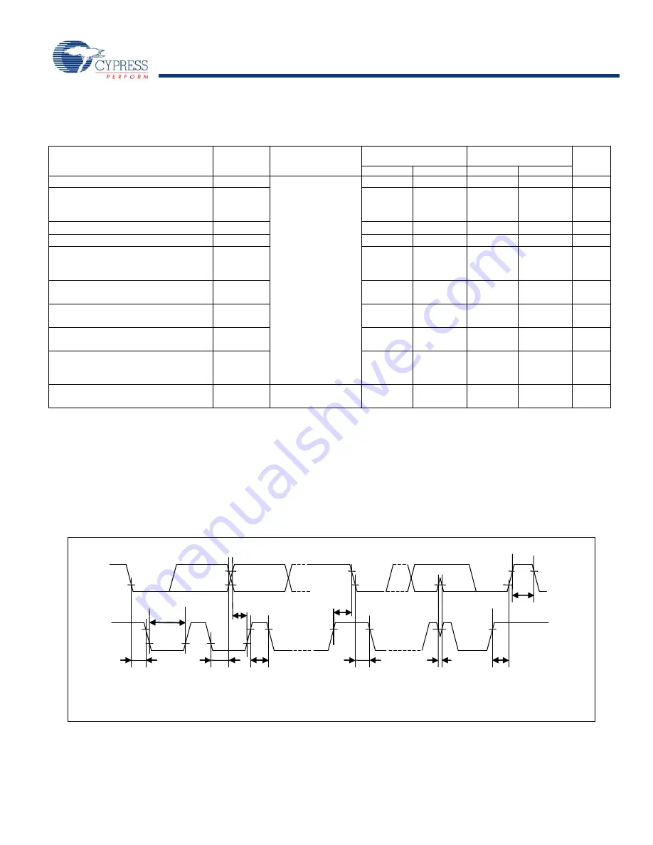
SDA
SCL
t
HDSTA
t
LOW
t
HDDAT
t
SUDAT
t
HIGH
t
SUSTA
t
HDSTA
t
SP
t
BUS
t
SUSTO


