background image

 
Cypress Envirosystems 
Doc # 152-10201-01 Rev 2.0  

BBS User Manual 

Page 6 

4.0


Setup Instructions 

4.1


Components 

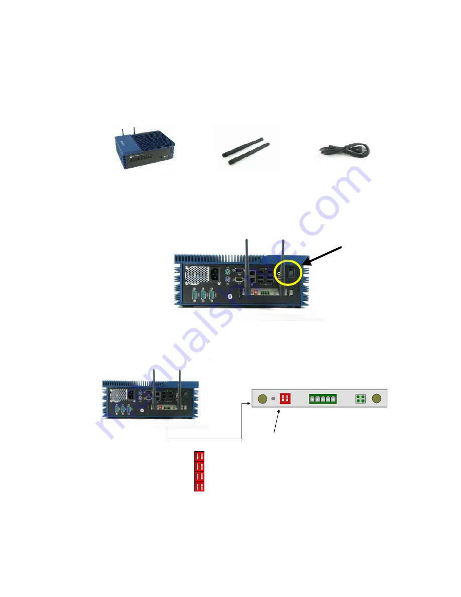
The BBS comes with the following components: 


BBS 


Antennas 


Power Cord 


Connect the antennas to the back of the BBS as shown below.  Then connect the power cord.  To turn on 
the BBS press the rocker switch highlighted below. 


Figure 3. BBS Power Switch Location 


To change the receiver channel frequency, set the DIP switches accordingly. 

Frequency 

Dip Switches


-Channel Set A (2,74)
-Channel Set B (6,78)
-Channel Set C (24,50)
-Channel Set D (30,54)

-Channel Set A (2,74)
-Channel Set B (6,78)
-Channel Set C (24,50)
-Channel Set D (30,54)


Figure 4. BBS Channel Frequency Configuration 


Power switch 

Summary of Contents for Blue Box Server

Page 1: ...Blue Box Server User Manual Doc 152 10201 01 Revision 2 0 Sept 2010...

Page 2: ...S FOR A PARTICULAR PURPOSE Cypress Envirosystems reserves the right to make changes without further notice to the materials described herein Cypress Envirosystems does not assume any liability arising...

Page 3: ...le 7 5 1 Starting the Program and General Navigation 7 5 2 Readings Page 7 5 3 Other Readings Pages 9 5 4 Configuring Nodes 11 5 5 Battery and Signal Strength Status 27 5 6 Alarms 27 5 7 View Alarm Hi...

Page 4: ...ed service technician for repairs See Section 10 0 Support for details 3 0 Description of BBS The Cypress Envirosystems Blue Box Server BBS is a flexible industrial server that collects wireless data...

Page 5: ...munication protocols e g OPC BACnet web services This configuration is depicted above as Option A For users who do not need to connect to an existing infrastructure the BBS can also serve as a standal...

Page 6: ...Then connect the power cord To turn on the BBS press the rocker switch highlighted below Figure 3 BBS Power Switch Location To change the receiver channel frequency set the DIP switches accordingly Fr...

Page 7: ...nce the web page loads the application opens to the READINGS page by default where you can find information on every data point or node in the system At the top of the READINGS page and every page in...

Page 8: ...xample Emergency Generator or Water Inlet Pressure Reading Most recent reading taken from the node Your service representative configures the update rate when the system is installed Units Unit of mea...

Page 9: ...hlighted in Yellow No Data This status is displayed if a Field Device has been configured on the BBS but no data has ever been sent from that field device The Row will be highlighted in gray OK This i...

Page 10: ...ems Doc 152 10201 01 Rev 2 0 BBS User Manual Page 10 Figure 8 The Wireless Steam Trap Monitor WSTM Readings Page Figure 9 Wireless Freezer Monitor WFM Readings Page Figure 10 Wireless Battery Monitor...

Page 11: ...he trap is building up condensate on the inlet The row is highlighted in red Out of Service There is no steam going to the trap It is not being used in the system The row is highlighted in blue Offlin...

Page 12: ...hown in Figure 13 below It has two clearly defined sections a top section where you can add and delete individual or multiple nodes and a bottom section that displays all the nodes in the system that...

Page 13: ...start transmitting data but the BBS must be configured to collect data for that device To add a node enter the new Node ID and press the Add button This will bring up a pop up dialog box See Figure 1...

Page 14: ...eam Trap node Enter Node1 and Node2 that will be used to calculate the reading for new node E g Node3 Node1 Node2 Precision Precision is used to set the number of decimal places to display on the read...

Page 15: ...ngineering reading These can be either noted down from the data sheet or the actual reading from the device E g For WTR type 0 10 V Volts1 0 Volts2 10 35 Value1 0 0001 Value2 1000 WTR One Point Calibr...

Page 16: ...mal places will be displayed depending on how large or small the reading value is at the time Update Rate Update rate as it has been configured on the field device duration of time between samples Thi...

Page 17: ...For WTR type 0 10 V Volts1 0 Volts2 10 35 Value1 0 0001 Value2 1000 WTR One Point Calibration Check this box if a 1 point calibration can be done This is typically used for calibrating thermocouples O...

Page 18: ...Gauge The user will either specify the type of measurement such as PSI H2O Inch LBS or a binary type TRUE FALSE ON OFF or ACTIVE INACTIVE In case of Binary unit type the Unit column display is empty i...

Page 19: ...y works when SMS Alarm is checked Min Alarm Threshold This is a specified lowest allowable value If the node reading drops below this number an alarm condition is created Max Alarm Threshold This is a...

Page 20: ...t 1 2 Volts 0 Value 0 Volts 5 Value 20 2 1 High Stage Compressor Current A WFM Opt 1 2 Volts 0 Value 0 Volts 5 Value 20 3 1 Freezer Temp C or F WFM Thermocouple Type K N A N A 4 1 Door Switch Binary O...

Page 21: ...y works when SMS Alarm is checked Min Alarm Threshold This is a specified lowest allowable value If the node reading drops below this number an alarm condition is created Max Alarm Threshold This is a...

Page 22: ...actor that is used internally for the correction Ok Save data but keep window open Close Don t save any data just close dialog Refresh Get the latest data from the database Table 5 WFM Node configurat...

Page 23: ...the list Orifice size Size of the orifice on the steam trap Dropdown list of user configured orifice sizes See the section on Site Settings WSTM tab Figure 26 for information on how to add or remove s...

Page 24: ...lue the trap is considered to be leaking or blowing Outlet Temp Max out of service temperature Maximum outlet temperature where the trap is considered out of service Above this value the Max Good temp...

Page 25: ...signed to the WSTM 5 4 2 3 1 1 Add Edit Delete Alarm Profiles To add an alarm profile from the WSTM Node Configuration Dialog screen click New and the alarm profile details will be displayed as seen i...

Page 26: ...ter the information to the Nodeconfiguration txt file This file is a tab separated text file that lists all the configuration parameters An example file is shown in Figure 19 Use the Upload button to...

Page 27: ...l strength of the last hop for each node Figure 20 Battery and Signal Strength Stauts 5 6 Alarms One of the benefits of Cypress Envirosystems Web Console is it immediately alerts you to potential prob...

Page 28: ...SMTP server To use the local SMTP server select the Use Local SMPT Server for Email Alarms Check box and fill in the appropriate SMPT info Figure 21 You can change the name that appears in the right...

Page 29: ...the last two hours for all nodes You can specify the time period and the nodes that you want to see an alarm history for by using the dialog box at the top of the page as shown in Figure 23 Figure 23...

Page 30: ...ge in the Main Menu This displays the Alarm History page A green Alarm Reset button is located at the top of this page 2 Click the green Alarm Reset button This will take you to the Alarm Reset page 3...

Page 31: ...er names in the WSTM Readings tab For all the dropdown menus in the WSTM Node configuration dialog the user can modify the entries from the WSTM Categories window on the WSTM Settings tab as seen in F...

Page 32: ...de the United States Command Function CYWGR AS SiteID NodeID Find Node status for specified NodeID CYWGR TR SiteID NodeID Get Node reading for specified NodeID CYWGR AR SiteID NodeID Reset Alarm for s...

Page 33: ...ale uncheck the checkbox and the Min and Max fields will enable Min If Auto Scale is turned off the user must specify the min Y value on the graph Max If Auto Scale is turned off the user must specify...

Page 34: ...n the graph click on a point The node ID number the timestamp and the value display on the top left corner of the graph 5 10 3 Zoom To zoom hold down the left click button on a point and drag the poin...

Page 35: ...cify the node IDs you want to display You can select nodes individually using the List of Nodes drop down list or enter the node ID number manually or check the box next to Select All Nodes If you sel...

Page 36: ...2 Reports An executive summary is available for WSTMs which gives an overall status of all the steam traps that are currently being monitored An energy summary is calculated which shows amount of stea...

Page 37: ...configure the firewall as needed 8 0 Troubleshooting I get an error message when I try and enter an email address into the SMS Alert Phone number is a required field If you do not enter a phone numbe...

Page 38: ...optional encryption and minimal interference with existing wireless systems for additional details please see FAQ at www cypressenvirosystems com Approvals FCC Class B compliant RoHS ETSI compliant Po...

Reviews: