


CY8CKIT-026 CAN and LIN Shield Kit Guide, Doc. No. 002-03798 Rev. *C
19
Hardware
3.2.5
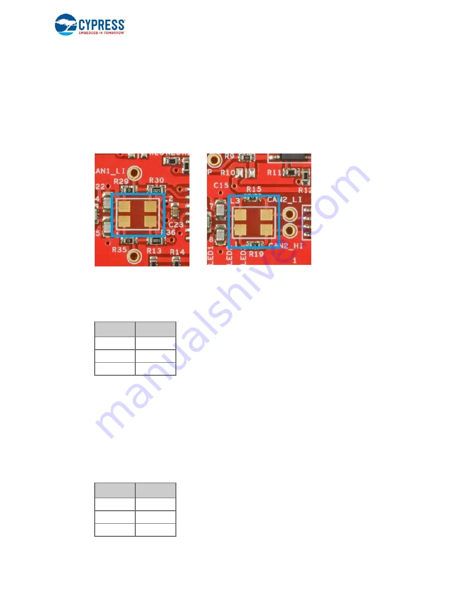
Choke Footprint
A footprint for a common-mode signal suppression choke is available on the shield board for both
the transceiver circuits, but these are not populated. These footprints can be populated with a
B82789C0 (or equivalent) choke to suppress common-mode signals on the CAN bus.
If a choke
component is mounted on the L2 footprint (for CAN1 transceiver), resistors R29 and R35
must be removed from the board. If a choke component is mounted on the L3 footprint (for
CAN2 transceiver), resistors R15 and R19 must be removed from the board
. The choke
component has no effect if these two resistors are not removed.
Figure 3-5. Choke Footprints for CAN1 and CAN2 transceivers
3.2.6
CAN Signal Connector for CAN1 Transceiver
shows the pinout of the 3-pin female CAN signal connector (J19) on the shield board.
CAN1_TX and CAN1_RX pins needs to be connected to the CAN TX pin, CAN_RX pin of the PSoC
(microcontroller) respectively, using external connecting wires. CAN1_ER pin is used for error
indication which should be connected to a GPIO pin of the microcontroller. These connections are
not hard-wired on the board so that maximum flexibility for the CAN pin placement in the
microcontroller is provided.
3.2.7
CAN Signal Connector for CAN2 Transceiver
shows the pinout of the 3-pin female CAN signal connector (J9) on the shield board.
Table 3-2. CAN1 Signal Connector Pinout
Pin
Signal
1
CAN1_TX
2
CAN1_RX
3
CAN1_ER
Table 3-3. CAN2 Signal Connector Pinout
Pin
Signal
1
CAN2_EN
2
CAN2_TX
3
CAN2_RX


