•
key +
key
During power-up, if both keys are held down, the printer enters the print
setup routine. Following the print-out of the setup report, the printer re-
mains in standby until a key is pressed or signals arrive from the serial
port; each 10 characters it prints out hexadecimal and ASCII codes (if
the characters are underlined, the receive buffer is full); see Receive
buffer hexidecimal print-out.
To entry in the notch sensor autocalibration phase (printer option 0103) press the LINE FEED key during the
printer power-up. After the beginning of the font test press, at the same time, the LINE FEED key and the FORM
FEED key. At the end of the font test the printer begin the notch threshold autocalibration.
The “Power On” LED (green) indicates that the printer is on.
•
The Paper Low LED (red) indicates that the paper is about to run out.
•
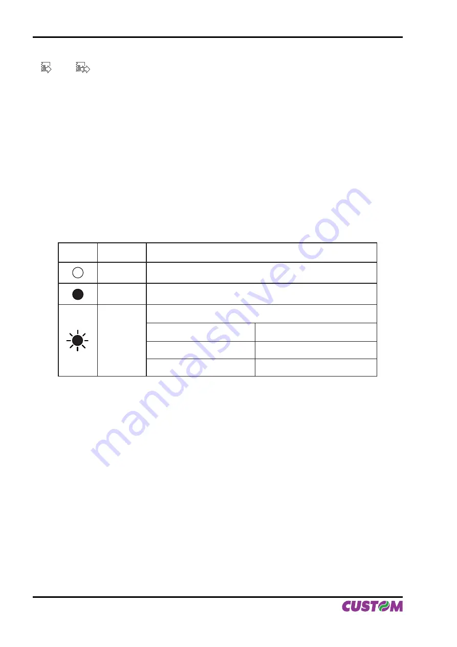
The “Status” LED (yellow) indicates printer status; the check is made on-line. Given in the table 1 are the
•
various LED signals and the corresponding printer status.
STATUS
LED
COLOUR
DESCRIPTION
OFF
Printer malfunction
ON
Printer ON - no malfunction
BLINKING
RECOVERABLE ERROR
Fast
Overheating
Slow (for extended period)
“No Paper” message
Slow (for short period)
Printing head turned upwards
(Tab.1)
INTRODUCTION
4 VKP112
User Manual
Summary of Contents for VKP112
Page 1: ...OEM USER MANUAL VKP112 VKP112 Command Reference DOMC 0001e ...
Page 8: ...Blank page TABLE OF CONTENTS ii VKP112 User Manual ...
Page 19: ...3 4 Fig 1 9 Fig 1 10 1 INSTALLATION AND USE User Manual VKP112 1 7 ...
Page 21: ...P3 P4 P5 Fig 1 13 Fig 1 14 Fig 1 15 1 INSTALLATION AND USE User Manual VKP112 1 9 ...
Page 23: ...1 3 VRRR 2 Fig 1 18 Fig 1 19 Fig 1 20 1 INSTALLATION AND USE User Manual VKP112 1 11 ...
Page 26: ...Blank page 1 INSTALLATION AND USE 1 14 VKP112 User Manual ...
Page 32: ...Blank page 2 INTERFACES 2 6 VKP112 User Manual ...
Page 36: ... Fig 3 2 Fig 3 3 Fig 3 4 3 TECHNICAL SPECIFICATIONS 3 4 VKP112 User Manual ...
Page 37: ... Fig 3 5 Fig 3 6 3 TECHNICAL SPECIFICATIONS User Manual VKP112 3 5 ...
Page 38: ...Blank page 3 TECHNICAL SPECIFICATIONS 3 6 VKP112 User Manual ...
Page 42: ...Blank page 4 CHARACTER SETS 4 4 VKP112 User Manual ...
Page 46: ...Blank page APPENDIX A ACCESSORIES AND SPARE PARTS A 4 VKP112 User Manual ...
Page 47: ......


