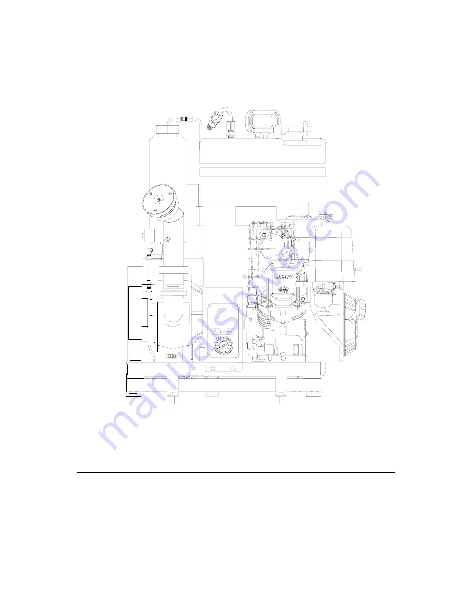
background image

DYNA-FOG


MINI-PRO 8HP


MODEL 2992 SERIES 3 (DIAPHRAGM PUMP) 

ULV AEROSOL APPLICATOR 


MANUFACTURED BY : 


CURTIS DYNA-FOG, Ltd.


17335 U.S. Highway 31 North 

WESTFIELD, INDIANA, U.S.A. 


INNOVATORS OF SPRAYING AND FOGGING DEVICES


OPERATION, MAINTENANCE AND SPARE PARTS MANUAL


MACHINE SPECIFICATIONS 

FOR MINI-PRO 8HP

TM

  , MODEL 2992, SERIES 3


TM 

 ® 

Summary of Contents for DYNA-FOG MINI-PRO 8HP 3 Series

Page 1: ...V AEROSOL APPLICATOR MANUFACTURED BY CURTIS DYNA FOG Ltd 17335 U S Highway 31 North WESTFIELD INDIANA U S A INNOVATORS OF SPRAYING AND FOGGING DEVICES OPERATION MAINTENANCE AND SPARE PARTS MANUAL MACHINE SPECIFICATIONS FOR MINI PRO 8HPTM MODEL 2992 SERIES 3 TM ...

Page 2: ...TY PRECAUTIONS 12 MACHINE OPERATION 14 PRE SPRAY CHECK LIST 15 ENGINE PREPARATION 16 STARTING THE ENGINE 17 BLOWER LUBRICATION 18 MEASURING LIQUID FLOWABILITY 19 COMMONLY USED CHEMICALS VMD 21 REMOTE CONTROL BOX FUNCTIONS 22 FILTER SILENCER 23 BLOWER FILTER ASSEMBLY 23 FORMULATION FILTER 24 IN LINE FILTER 24 HI FLEX COUPLING INSTALLATION INSTRUCTIONS 25 3 WAY VALVE 28 2 ...

Page 3: ...AGRAM 36 EXPLODED PARTS DIAGRAM 37 ENGINE ASSEMBLY 38 COUPLING 38 BLOWER ASSEMBLY 39 ULV NOZZLE ASSEMBLY 40 BLOWER FILTER ASSEMBLY 40 BOOM ASSEMBLY 41 FORMULATION TANK ASSEMBLY 42 3 WAY VALVE ASSEMBLY 43 PLUMBING DIAGRAM 44 PLUMBING DIAGRAM PARTS LIST 45 CONNECTIONS STEEL PLASTIC 46 WHEEL KIT DIAGRAM 47 WHEEL KIT PARTS LIST 48 ADJUSTABLE BOOM FOR MINI PRO OPTIONAL 49 3 ...

Page 4: ...ting the need for unreliable timing pins Original Roots impeller design dynamically balanced and center timed Long life anti friction bearings All bearing points are engineered for long service life FORMULATION PUMP Self priming positive displacement Diaphragm Pump Viton elastomers dry running capabilities driven by a 12 VDC permanent magnet motor The pump head includes an internal pressure relief...

Page 5: ...REMOTE CONTROL Machine ON OFF Spray ON OFF Engine Start The remote control can be removed from the machine by disconnecting an electrical quick coupling at the end of the cable FRAME High strength welded square tube frame including cross members for additional strength The compact base dimensions permit easy handling and mounting Each machine includes four heavy duty rubber feet for even support a...

Page 6: ...erator model 2992 should be operated and maintained in compliance with this manual Insecticides must be applied in compliance with their label instructions WARNING Read and thoroughly understand all information cautions and warnings on the formulation label which may affect personal safety Know any dangers of the solution used and know what to do in case of an accident involving the solution Alway...

Page 7: ...positive displacement diaphragm pump that draws the formulation from the tank through a filter and 3 way valve and into restricting orifice solenoid valve and the nozzle The nozzle has six stationary fins that create a swirling effect of the air mass as it leaves the nozzle In the center of this swirling air mass is a liquid supply tube The spray tube directs the formulation into the air mass wher...

Page 8: ...8 ...

Page 9: ...ding to the following instructions CHARGING THE BATTERY DANGER POISON Batteries produce explosive gases Keep sparks flame and cigarettes away Ventilate when charging or using in an enclosed space The battery contains Sulfuric Acid which causes severe burns If acid contacts eyes skin or clothing flush well with water For contact with eyes get immediate medical attention Keep battery and acid away f...

Page 10: ...hine in same position as it was before being removed terminals side of battery is facing the engine H Connect the RED positive cable to the positive terminal of the battery and fasten it securely with the hardware provided I Connect the BLACK negative cable to the negative terminal of the battery and fasten it securely with the hardware provided CAUTION When installing the battery connect the nega...

Page 11: ...ote cable When routing the cable to the vehicle cab do not allow the cable to be exposed to any sharp edges Avoid sharp bends when routing the cable Once the cable has been routed to the cab reseal all drilled openings to prevent moisture and or exhaust gases from entering the cab 3 Using the 3 hold down brackets used for mounting the machine to the shipping skid securely mount the machine to the ...

Page 12: ...ON DO NOT OPERATE ENGINE WITHOUT MUFFLER NOTE The engine is equipped with a muffler that has spark arrestor which is required in some States DO NOT TOUCH HOT MUFFLER CYLINDERS OR FINS AS CONTACT MAY CAUSE BURNS EXCEPT FOR ADJUSTMENT DO NOT OPERATE THE ENGINE IF AIR CLEANER OR COVER DIRECTLY OVER THE CARBURETOR AIR INTAKE IS REMOVED DO NOT RUN THE UNIT IF THE COUPLING GUARD IS REMOVED DO NOT TAMPER...

Page 13: ...pends upon the chemical used mist density and the length of time of direct exposure IT IS THE OPERATOR S RESPONSIBILITY TO DISCOURAGE ANYONE FROM PLAYING IN THE MIST OR BEING NEAR THE MOVING VEHICLE 6 FORMULATIONS Ensure that formulations are applied only in strict compliance with the formulation label as well as local state and federal regulations and that these formulations are dispersed only by...

Page 14: ...REPARING TO DISPENSE FORMULATION READ AND THOROUGHLY UNDERSTAND ALL INFORMATION CAUTIONS AND WARNINGS ON THE FORMULATION LABEL WHICH MAY AFFECT PERSONAL SAFETY KNOW ANY DANGERS OF THE SOLUTION USED AND KNOW WHAT TO DO IN CASE OF AN ACCIDENT INVOLVING THE SOLUTION ALWAYS USE THE APPROPRIATE SAFETY EQUIPMENT AND DRESS ACCORDING TO THE CHEMICAL FORMULATION WHICH IS BEING USED WARNING DO NOT USE ANY S...

Page 15: ...nted securely and cable connections are proper and tight 9 Verify that all safety equipment is in place and is in proper working order 10 Verify that the flow rate control has been calibrated and is dispensing formulation in accordance with the manufacturers label requirements CAUTION BEFORE PROCEEDING WITH ANY SPRAYING OPERATION THE OPERATOR SHOULD BE THOROUGHLY FAMILIAR WITH STARTING AND STOPPIN...

Page 16: ...engine off Wait 30 seconds and check oil level Add oil to bring level to Full mark on dipstick if required NOTE Engine is shipped from factory without oil Before starting the engine check oil level Fuel Recommendations The engine will operate satisfactorily using any automobile gasoline Use clean fresh lead free gasoline with a minimum of 85 octane for overhead valve engines Leaded gasoline may be...

Page 17: ...on TURN ON RUN THE KEY SWITCH Position key switch on engine to ON This switch is located next to the starter button Also turn ON the fuel valve START ENGINE Activate the spring loaded starter switch on the engine or activate the rocker switch on the remote control box to the start position NOTE To prevent overheating the engine starter motor do not activate the motor longer than 15 seconds at a ti...

Page 18: ...apacity 3 4 Oz 1 Liters Proper lubrication is usually the most important single consideration in obtaining maximum service life and the most satisfactory operation from the unit Unless operating conditions are quite severe a weekly check of gearhouse oil level and necessary addition of lubricant should be sufficient However oil should be changed after initial 100 hours Of operation Thereafter a co...

Page 19: ...ifferent viscosities Viscosity is defined as a fluids resistance to flow commonly measured in units of a centipoise CP Generally the thicker the liquid the greater the viscosity and the higher the CP number Examples of some liquid viscosities are LIQUID VISCOSITY CP WATER 1 DIBROM 3 4 DOW MFC 3 4 PYRETHRIN RESMETHRIN 6 7 DURSBAN 1 5 ULV 12 14 TECHNICAL MALATHION 28 By measuring the flowability of ...

Page 20: ...fied on the formulation label This includes driving your vehicle at a rate slower than what is specified CAUTION The rates on the next page are examples of typical application rates found on their respective formulation labels Refer to the label of your formulation to determine the actual application rate before calibrating your machine to any of the above flow rates Once the flowability of the fo...

Page 21: ...4 3 6 5 10 20 MMD 6 5 7 15 _________________________________________________________________________________ Calculations Barrier Spray Label Permethrin 57 Diluted 1 9 Application Rate Up to 90 Oz linear mile traveled 5 MPH 083 mi min vehicle speed the time to travel 1 mile 1 mile 083 mi min 12 05 min linear mile 12 05 min linear mile times Flowrate 90 oz linear mile Flowrate 5 MPH 90oz linear mi ...

Page 22: ... D green light indicating power is ON Be sure to turn OFF after operation of machine to prevent discharging battery START Applies system power to starter solenoid to start the gasoline engine SPRAY ON Applies 12V DC on pump motor and 12V DC to spray switch red light and opens the 2 way solenoid valve on nozzle boom SPRAY OFF Removes power to pump motor turning spray switch red light off and closin...

Page 23: ...lockwise 2 Remove wing nut and washer 3 Remove outer shell cover 4 Remove stainless element C Inspection and Cleaning 1 Clean the stainless screen in an approved solvent dry with compressed air or shake to remove excess solvent and allow to dry naturally Inspect the screen for defects that may permit dirt or other foreign particles to enter the air blower 2 Inspect the outer shell cover for cracks...

Page 24: ...62558 5 TO REMOVE AND CLEAN THE SCREEN 1 Loosen and remove the bottom portion bowl from the housing body being careful not to lose the Aflas gasket seal ring 2 Remove and clean the fine wire mesh stainless steel screen 3 Check the Aflas gasket seal ring and replace if necessary CAUTION Do not over tighten as damage the Aflas gasket seal ring may occur Over tighten will not improve the seal NOTE If...

Page 25: ...ews as much as possible or disassemble Slip flange over QD bushing and assemble in the following manner CAUTION NEVER ALLOW THE FLANGE ASSEMBLY TO BE DRAWN IN CONTACT WITHTHE FLANGE OF THE QD BUSHING THERE SHOULD BE A GAP FROM 1 8 TO 1 4 BETWEEN THEM IF THE GAP IS CLOSED THE SHAFT IS SERIOUSLY UNDERSIZE Bolts of QD Bushing 10 24 grade 5 Bolts of Flange Assembly 20 Socket Head Cap equivalent to gra...

Page 26: ...flanges should be aligned so that the dimensions at all four places do not vary more than 1 32 for best results Check parallel misalignment by laying the straight edge across the flange O D several places around the circumference of the coupling Parallel misalignment not to exceed 1 32 for best results FOR PARALLEL AND NON PARALLEL SHAFTS For the longest coupling life it is always best to align co...

Page 27: ...ange assemblies and install the new flexible element according to step 5 and 6 If necessary to replace flange assembly screws use only grade 8 or equivalent IMPORTANT NOTICE Because of the possible danger to person s or property from accidents which may result in the use of this product it is important that the Hi Flex coupling be used in accordance with the engineering information specified in th...

Page 28: ... Way valve is working to dispense formulation valve lever pointing down Upon the activation of the Spray button the diaphragm pump will draw liquid from the formulation tank and pass through the formulation filter 3 way valve and pump IN port 28 IMPORTANT Always turn the spray switch OFF at the remote control before moving the lever of the 3 way valve The 3 way valve should be located with the lev...

Page 29: ...for 3 to 5 minutes 3 WAY VALVE WORKING IN FLUSH POSITION In above diagram the 3 Way valve is working to dispense Flush solution valve lever pointing up Upon the activation of the Spray button at the remote control box the diaphragm pump will draw liquid from the flush tank and pass through the flush filter 3 way valve and pump IN port CAUTION Never handle any parts on the machine that come in cont...

Page 30: ...diaphragm pumping system the flow rate of the liquid is controlled by a needle valve as a bypass regulator between the suction IN line and pressure OUT line of the pump The more turns that the valve is open the lower the output that can be achieved Additionally interchangeable restricting orifice is in the line to allow a fine regulation to the needle valve Every restricting orifice gives a specif...

Page 31: ...31 ...

Page 32: ...y switch to the ON position Let the machine spray for 30 seconds to remove any air bubbles from the tubing and then turn the Spray OFF and the Machine OFF Step 4 Disconnect the 3 8 tubing from the plastic elbow nut at the bottom of the nozzle as shown in Figure 2 Step 5 Place the 3 8 tube connected to the Orifice Fitting into a graduated cylinder Figure 3 Step 6 Start the machine and place the Spr...

Page 33: ...following 1 Remove the four screws that hold the enclosure cover to the base plate see left side diagram Carefully remove the cover taking into account that some wires are still retaining the cover to the wiring of the pump 2 Remove the orange wire see right side diagram from the switch terminal ANO3 normally opened and remove the piece of tubing from terminal ANC2 normally closed Place the orange...

Page 34: ...G FLOW FLOW VALVE SETTING FLOW FLOW TURNS OPEN ML MIN OZ MIN TURNS OPEN ML MIN OZ MIN FULLY OPENED 490 16 3 FULLY OPENED 670 22 3 4 500 16 7 4 1 4 680 22 7 3 3 4 520 17 3 4 750 25 0 3 1 2 570 19 0 3 3 4 770 25 7 3 1 4 640 21 3 3 1 2 820 27 3 3 670 22 3 3 1 4 930 31 0 TOTALLY CLOSED 710 23 7 3 960 32 0 TOTALLY CLOSED 1100 36 6 ORIFICE 59 NO ORIFICE VALVE SETTING FLOW FLOW VALVE SETTING FLOW FLOW TU...

Page 35: ... 6 7 Rotate bearing cover 10 so access notch is aligned with cam bearing screw loosen setscrew with a 1 8 Allen wrench and slide pump lower housing assembly from motor shaft 8 After removing the cam bearing from the outer piston set the inner piston screws are now visible remove both flat head screws The outer piston set can now be removed from the inner pistons Diaphragm Cam Assembly 6 1 Place he...

Page 36: ...36 ...

Page 37: ...019 1 CLAMP V INSERT 11 64630 2 1 NOZZLE ASSEMBLY 12 63245 4 1 GAUGE PRESSURE 13 63655 1 GUARD ASSEMBLY COUPLING 14 63870 1 PLATE ASSEMBLY ENGINE BLOWER 15 N62712 1 1 SOLENOID AY STARTER 16 64828 1 POST ASSEMBLY FORMULATION 17 62875 2 2 STRAP ASSEMBLY 18 63327 4 FOOT EPDM RUBBER 19 64826 1 POST ASSEMBLY FORMULATION 20 64004 1 FORMULATION TANK ASSEMBLY 15 GALLON 21 64821 1 BRACKET FLUSH SHORT 22 64...

Page 38: ...ENGINE 8 HP 2 1 62549 SPARK ARRESTOR 3 1 63868 1 BUSHING JA QD 1 4 1 63865 FLANGE 50JA ITEM PART NO DESCRIPTION 1 63868 1 BUSHING 1 BORE JA QD 2 63865 FLANGE ASSEMBLY 50 JA 3 63862 INSERT COUPLING 4 63865 FLANGE ASSEMBLY 50 JA 5 63863 1 BUSHING 5 8 BORE JA QD COUPLING MINI PRO 38 ...

Page 39: ...USHING JA QD 5 8 3 1 140879 SET SCREW 10 32 x 3 16 4 1 63865 FLANGE AY 50JA 5 1 63056 NIPPLE CONN WELD AY 6 1 63059 1 ELBOW 90 STREET 2 7 1 22183 2 TEE ORIFICE ASSEMBLY 8 3 63060 LOCKNUT 2 9 1 63606 BUSHING 1 1 2 x 2 NPT 10 1 63642 ELBOW 90 STREET 1 5 11 1 63604 FILTER AIR INTAKE 12 1 62613 LABEL CAUTION 39 ...

Page 40: ...O D 4 1 64160 DISC NOZZLE MACHINED 5 3 64643 SCREW 10 24X3 8 SST 6 3 64642 SCREW 6 32X3 8 SST 7 1 64601 CONE NOZZLE ANODIZED 8 1 422987 NUT JAM 5 16 24 BLOWER FILTER ASSEMBLY P N 63604 ITEM QUANTITY PART NUMBER ITEM DESCRIPTION 1 1 126177 20 WING NUT 2 1 446179 1 4 WASHER 3 1 63604 3 FILTER COVER 4 1 63604 2 FILTER ELEMENT 5 1 63604 1 BASE ASSEMBLY 40 ...

Page 41: ...ET ADAPTOR 5 2 G189772 SCREW 10 32 X 3 8 HEX 6 2 G120391 WASHER FLAT 7 2 G138479 WASHER LOCK 8 1 62584 17 TUBING 1 4 OD POLYP 12 9 1 62641 3 ELBOW 1 4MP 3 8 T 10 2 62582 1 NUT 25 PLST GRIP 11 1 62555 1 ELBOW UNION 1 4 T 12 1 62550 1 NUT 25 STL GRIP 13 2 B10100 10 O RING 14 1 G145463 NUT 1 4 TUBE 15 1 64634 BOOM AY WELDED 16 1 63019 CLAMP V INSERT 17 1 62814 PLUG 1 8 PIPE MOD 41 ...

Page 42: ... Formulation standpipe assy 1A B62545 1 Formulation standpipe 1B B62550 3 2 Nut Steel gripper 1C B62553 3 1 Connector union 3 8 T 1D A62573 2 1 Connector male mod 2 B64772 1 Bushing NL 3 4 MP 3 8 FP 3 C64002 1 Tank 15 Gal 4 A63904 1 Label formulation 5 B64077 1 Cap Assembly 42 ...

Page 43: ...LBOW 1 4MP 1 4T 2 1 ASC 35 ELBOW 1 4FP 1 4MP BRASS 3 1 N86196 VAVLE 3 WAY 4 1 64619 VALVE BRACKET 5 1 62592 FLUSH LABEL 6 1 63685 FORMULATION LABEL 7 1 62558 5 FILTER O RING 8 1 62554 4 ELBOW 1 4FP 3 8T 9 1 62641 3 ELBOW 1 4MP 3 8T 43 TO FORMULATION TANK TO FLUSH TANK TO INLET PORT OF PUMP ...

Page 44: ...44 ...

Page 45: ...62584 TUBE 1 4 OD 13 RM22083 TUBE 3 8 OD 14 22338 8 ORIFICE ASSEMBLY 28 15 RM 22083 TUBE 3 8 OD 16 62641 4 90 ELBOW 3 8 MP x 3 8 T 17 22235 VALVE METERING 18 63497 CHECK VALVE MP 3psi 19 62556 3 UNION TEE 3 8 T 20 62554 4 90 ELBOW 3 8 T x 1 4 FP 21 45744 NUT 3 8 T BRASS 22 45745 SLEEVE BRASS 3 8 23 48116 INSERT BRASS 3 8 24 RM22083 TUBE 3 8 OD 25 RM22083 TUBE 3 8 OD 26 RM22083 TUBE 3 8 OD 27 62641...

Page 46: ...SAMPLE CONNECTIONS USING STEEL PLASTIC GRIPPER NUT 46 ...

Page 47: ...47 ...

Page 48: ... 25 1 8 122007 BOLT 5 16 18x3 4 12 9 120214 LOCKWASHER SPLIT 5 16 ZINC 20 10 63963 CLEVIS ASSEMBLY 1 11 120696 BOLT 5 16 18 1 12 122017 BOLT 5 16 18x1 HEX 2 13 63967 CASTER LOCKING 2 14 63960 2 MOUNT CASTER RIGHT 1 15 63954 SPACER SWIVEL CASTER 2 16 122040 BOLT 5 16 18x1 1 2 HX 6 17 102569 SET SCREW 20 2 18 120396 WASHER FLAT 2 19 120378 NUT HEX 1 2 13 2 20 29669 WHEEL 12 DIA 2 21 63964 1 BRACKET ...

Page 49: ...E 7 2 B10100 10 O RING 8 1 B62550 1 NUT 250 STL GRIP 9 1 B62555 1 ELBOW UNION T 10 2 B62582 1 NUT 250 PLST GRIP 11 1 B62638 2 VALVE AY 2 WAY 12 1 B62641 2 ELBOW 1 4MP 1 4T 13 1 B62641 3 ELBOW 1 4 MP 3 8T 14 1 A62419 KNOB QK RELEASE 15 1 B62584 17 TUBING 1 4 OD POLYPROP 12 16 2 G189722 SCREW 10 32x3 8 HEX 17 2 G120391 WASHER FLAT 18 2 G138479 WASHER LOCK NOTE THE NOZZLE FACE PLATE HAS THE CENTER HO...

Page 50: ... aircraft can handle the amount of Flow rate as the ASC Atomizer Several accessories are available to meet your requirements Also available in 12 or 24 VDC see rotary atomizers above model ASC A20 COMBUSTION ENGINE DRIVEN ULV AEROSOL GENERATORS Truck mounted Units powered by 8 9 11 or 18 HP four cycle OHV Gasoline Engine Diesel version available One two or four nozzles Optional full remote control...

Reviews: