Optional Accessories
87
Cat. No. 01024000
Installing the Quality Monitor in the Controller
1. Open the controller door and use a sharp knife to cut out the rectangular portion of the front door label that cov-
ers the rectangular opening below the power on/off knob.
2. The controller comes with mounting brackets to attach it to the door of the controller and it comes with power
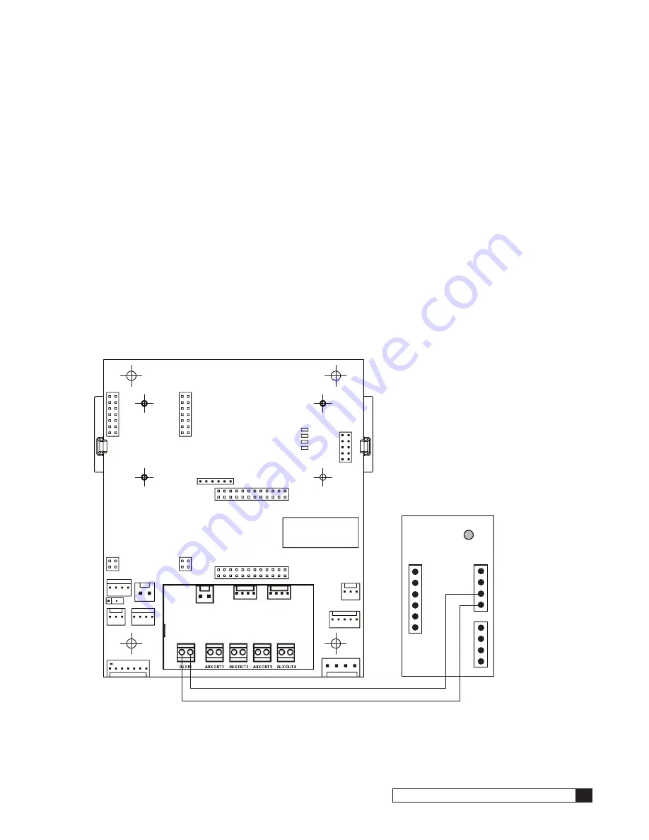
3. Connect the dry contact output terminals (terminal 3-NO in Figure 36) to the AUX-IN screw terminals on the
auxiliary input board P/N 01020748 in Figure 38 and install this input board into the back of the GBE board. The
contact output from the external quality sensor will close any time that the measured quality is above (worse
than) the user provided set point.
4. The External quality monitor uses the same probe that comes pre-installed in the Premier AutoDI system. It is
necessary, however, to cut off the connector on the ends of the probe wiring, remove the wire insulation from
the last 0.1” of each of the 4 colored wires, and then attach those wires to the screw terminals identified as
1-COM in Figure 36.
5. Use the Smart Controller menu to set up the sensor for the system.
When using an external quality monitor, the Smart Controller cannot display the measured quality (it is installed on the
external quality sensor display instead). The Smart Controller will only display that the quality is “OK,” meaning that the
measured quality is better than the set point, or “HIGH,” meaning it is worse than the quality set point. When using teleme-
try, the call-in information will also not include the measured quality value when using an external sensor.
P/N: XXXXXXXX rev. X
VENDOR: XXXXXX
DATE CODE: WK/YY
HEX FILE: XXXXXXXX rev. X
4 3 2 1
Dosing Contact
Quality Monitor
Auxiliary Board
GBE Circuit Board
AUX IN
Figure 38.
External Quality Monitor Wiring


