Chapter 1: Introduction
2
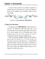
To achieve proper operation, the timeslot assignment of
transmit and receive sides must be the same and sequential,
otherwise, the multiplex and de-multiplex feature will not
work reliably.
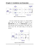
Figure 1-3: Typical Application of
MUX128/2*64
1.2 Data Port Interfaces
The data port of the
MUX128/2*64
is DCE and runs at a
fixed rate of 128Kbps in synchronous mode only. At the
receiving side, the incoming data is split equally, bit-for-bit, to
the A and B channels of the G.703/64K interfaces. When
receiving data from the G.703 channels, the data is
recombined to form the outputted 128Kbps stream.
There are 6 interface standards supported by the Data Port.
They are RS-530, RS-449, X.21, V.35, RS-232 and V.36.
The output connector for the Data Port is a standard DB25F
connector. Interface selection is provided by a combination of
DIP switch settings and physical adapter cables. For exact
DIP switch settings and cabling information, please refer to
Appendices A and B respectively.
Summary of Contents for MUX128
Page 1: ...INSTALLATION and OPERATIONMANUAL ...
Page 2: ......
Page 26: ...Appendix A DIP Switch Setting Tables 22 This page left blank intentionally ...
Page 34: ......
Page 35: ......


