Chapter 2: Installation and Operation
11
2.5 DIP Switches and Jumper Settings
2.5.1. Caution
To avoid accidental electrical shock, disconnect the
MUX128/2*64
power cord prior to opening the cover.
2.5.2. Procedure
a.
Turn power OFF. Disconnect the power cord from the AC
outlet.
b.
Loosen the thumb screws at the left/right of the rear panel.
c.
Remove the PCB assembly.
d.
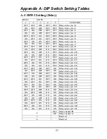
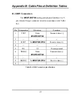
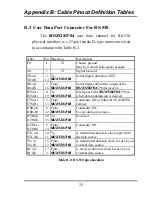
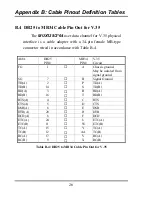
Adjust the DIP switches and jumper as required, according to
the tables in Appendix A.
e.
Replace the PCB and tighten the screws.
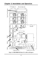
Referring to the following figure, three DIP switches are
used for configuration and are labeled DSW1 to DSW3. If a
DIP switch configuration is changed while the
MUX128/2*64
is in a powered on state, the effect will not be realized until
the unit is power cycled off then on.
The Logic Ground Jumper will connect (
CON)
or
disconnect (
DIS)
the
MUX128/2*64
logic ground from
chassis ground. Chassis ground is connected directly to the
ground post of the IEC power connector.
Summary of Contents for MUX128
Page 1: ...INSTALLATION and OPERATIONMANUAL ...
Page 2: ......
Page 26: ...Appendix A DIP Switch Setting Tables 22 This page left blank intentionally ...
Page 34: ......
Page 35: ......


