Chapter 2: Installation and Operation
14
Bit Error Rate Tester
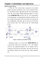
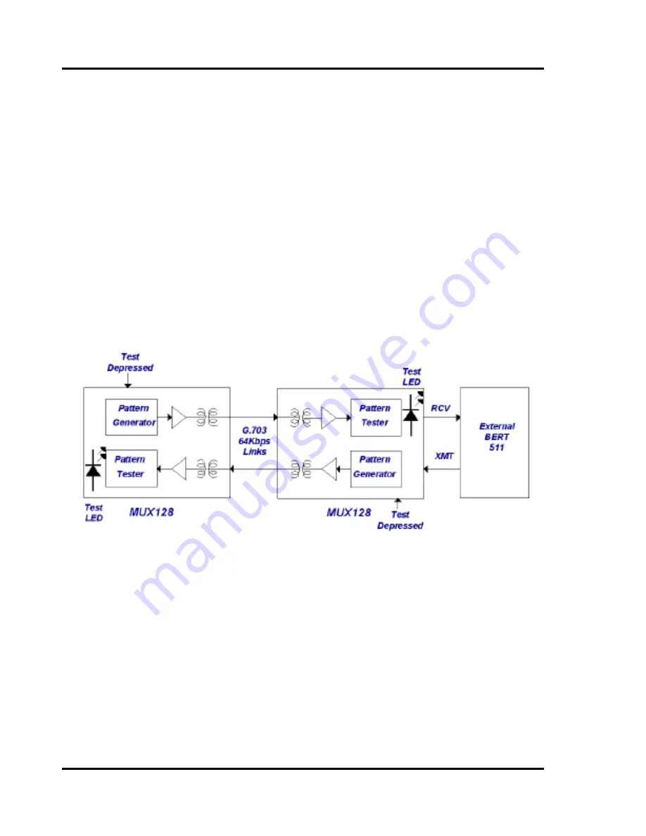
When the “Test” push-button is depressed, the internal
pattern generator and pattern tester will be activated and a
511 test pattern will be transmitted out the 64K co-directional
lines. The “Test” LED will light. Referring to figure 2-4, if the
remote
MUX128/2*64
unit also has its “Test” push-button
switch depressed, its internal pattern generator and tester will
be activated and its signal will be received by the local unit. In
this configuration, both units and the lines are tested. Both
units will have their “Test” LEDs lit and “Err” LEDs should
be off.
Figure 2-4: Back-to-back BERT testing
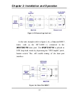
Referring to figure 2-5, if the remote
MUX128/2*64
unit
is placed into loop back by placing its “Loc ana loopbk”
switch in the depressed position, the 511 pattern will be
returned to the local unit and tested. This will test the local
unit and lines. If there are no errors, the “Err” LEDs should be
off.
Summary of Contents for MUX128
Page 1: ...INSTALLATION and OPERATIONMANUAL ...
Page 2: ......
Page 26: ...Appendix A DIP Switch Setting Tables 22 This page left blank intentionally ...
Page 34: ......
Page 35: ......

