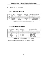
Appendix B. Interface Connections
34
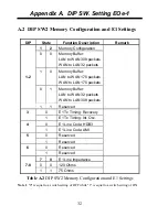
DIP Switches
Frame GND
jumper
B.2 E1 Line Frame Ground
To disable Frame Ground (Chassis) connections from the E1
signal carrying lines, remove the jumper on the JP1 header, located
close to the RJ-45 E1 connector. Signal line frame ground should only
be connected at one end of the E1 line to avoid ground loops and
ground potential differences between the each end of the line.
Figure B.1
Frame Ground Connection
B.3 Ethernet RJ-45 Connector
MDI MDI-X
1. Tx +
1. Rx +
2. Tx -
2. Rx -
3. Rx +
3. Tx +
6. Rx -
6. Tx -
Note: Ethernet does not use pins 4,5,7,8.
Summary of Contents for EOe-1
Page 1: ...USER MANUAL EOe 1 10 100Base Ethernet over G 703 Unframed E1 ...
Page 2: ......
Page 4: ......
Page 18: ...Chapter 1 Introduction 12 This page left blank intentionally ...
Page 26: ...Chapter 2 Installation 20 This page left blank intentionally ...
Page 43: ......


