Chapter 2. Installation
13
2.1 General
This chapter provides detailed instructions for mechanical
installation of the
EOe-1
. Following the completion of
installation, please refer to Chapter 3 for operating information.
2.2 Site Preparation
Install the
EOe-1
within reach of an easily accessible
grounded AC outlet. The outlet should be capable of furnishing
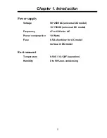
90~250VAC. DC power capable units connect via terminal block
connection. Allow at least 10 cm (4 inch) clearance at the rear of
the
EOe-1
for signal lines and interface cables.
2.3 Mechanical Assembly
The
EOe-1
is designed for tabletop or bench installation,
and is delivered completely assembled. No provisions are made
for bolting the
EOe-1
to the tabletop.
2.4 Electrical Installation
Power connection
AC power is supplied to the
EOe-1
through a standard 3-
prong IEC receptacle. (Refer to Figure 2.1) The
EOe-1
should
always be grounded through the protective earth lead of the
power cable or via Frame Ground connection.
Summary of Contents for EOe-1
Page 1: ...USER MANUAL EOe 1 10 100Base Ethernet over G 703 Unframed E1 ...
Page 2: ......
Page 4: ......
Page 18: ...Chapter 1 Introduction 12 This page left blank intentionally ...
Page 26: ...Chapter 2 Installation 20 This page left blank intentionally ...
Page 43: ......


